


 In the present world, highly affected by pandemic, there is a huge spike in Covid-19 infection cases in many places. With limited resources the fight against Covid-19 virus is an unexpected challenge for the whole world. As we all saw, arranging oxygen cylinders for loved ones became a difficult task a few months ago in India. The patients and their close relatives suffered badly, instead of providing moral support to the patients, when they could not arrange oxygen cylinders.
To get rid of this situation, this DIY project tries to help through details about assembling an oxygen concentrator at home. With the help of easily available parts, one can make an oxygen concentrator with enough capacity to support a Covid-19 or any other patient in need of oxygen.

Circuit and working
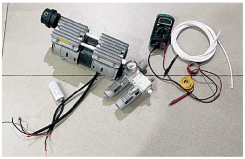
This oxygen concentrator can be built using an Arduino Uno, 12V DC power supply, control relay, solenoid valves, air compressor, air filtration unit, flow control valve, membrane housing as canisters, PU fittings, and zeolite sieves. Electronic control circuit is the main part of the oxygen concentrator. Oxygen is supplied (to the patient) through the solenoid valve outlets, which are controlled by the circuit presented here.
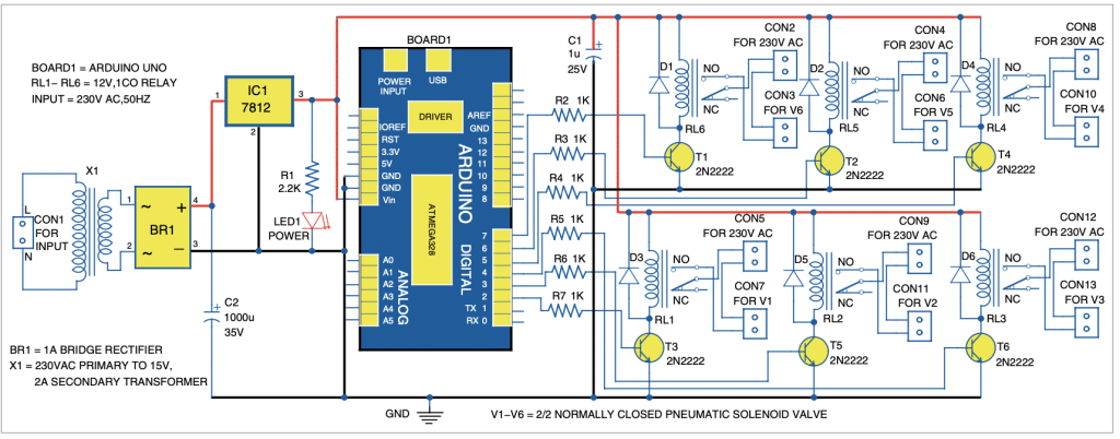
The circuit diagram of oxygen concentrator controller is shown in Fig. 1. It is built around 15V AC step-down transformer X1, bridge rectifier BR1, 12V voltage regulator (7812) IC1, Arduino Uno Board1, solenoid valves V1 through V6, 5mm LED (LED1), 2N2222 transistors T1 through T6, and 12V relays RL1 through RL6.

Arduino Uno
Arduino Uno board is connected to control relays. It is preprogrammed with delays to switch control relays on and off as programmed.
12V power supply
This power supply is used to provide power to Arduino Uno and control relays. It comprises a 15V/2A step-down transformer, full bridge diode rectifier BR1, 1000µF/35V and 1µF/25V capacitors, 12V voltage regulator IC 7812. The step-down transformer reduces the 230V AC input to 15V AC. This AC is converted to DC by full bridge diode rectifier, which is filtered using capacitor C2. IC 7812 regulates the voltage to 12V DC.
Relay
Relay being an electromagnetic switching device, it provides electrical isolation between the controlling and output circuits. It is controlled/triggered by a low DC voltage while its contacts can handle a high current flow with total electrical isolation from the delicate low-power electronic circuit. 12V DC SPDT relay is used here to switch the solenoid valves on and off on receipt of electrical pulses.
Zeolite molecular sieves
The sieves have pores of precise and uniform size and structure. These separate nitrogen and oxygen in the atmospheric air by disallowing molecules of nitrogen, which are slightly larger in size than the pores. Nitrogen molecules having higher electrostatic field react with cations of zeolite that are larger than the pores and get absorbed, thus cannot pass through. Only oxygen passes through the pores as its molecules measure 292 picometres compared to 300-picometre size of nitrogen (a difference of 2.6% only!) Air compressor. It is operated by an electric motor to suck atmospheric air and compress it in its chamber.
Filtration unit
It is used to filter contamination from the compressed air and also to separate moisture from the compressed air, which is collected in a bowl attached to it. Water thus collected needs to be drained out.
Solenoid valves
These are electromechanical devices that are used to control the flow of air on receipt of electrical signals. Here 2/2 pneumatic control normally-closed valves are used, which means they have two ports for connection with two possible positions. So, they are spring loaded.
Pressure swing adsorption (PSA)
This technique is used to separate specific gases from a mixture of gases under pressure with the help of specific sieves required for the purpose. For an oxygen concentrator, 13x zeolite molecular sieves are used. For higher oxygen concentration, lithium enriched zeolite molecular sieves can be used.
In this technique, at least two canisters or towers filled with sieves are used. Compressed air is supplied to one of the canisters and the other canister gets the oxygen output from the first canister for further filtering. This is done as concentration of nitrogen gas gradually increases in the first canister, which may affect the output oxygen’s purity and concentration. The direction of the air flow is controlled using solenoid valves, which give signals as per program.
The sieves have limited adsorption capacity, so to get specific flow rate the quantity of sieves needs to be calculated. For that you need to refer sieve supplier’s datasheet to know sieve quantity required to produce, say, one litre per minute (1 LPM) oxygen at specific concentration limit. For example, 700 grams of sieves are required for 1 LPM oxygen at 94% concentration. For oxygen concentrator with 5 LPM flow, you need 700× 5=3,500gm in one canister. So, for two canisters, a total of 3,500×2= 7,000gm sieves are needed.
Software
Arduino program oxygen_concentrator_diy.ino was used for the prototype. It must be uploaded to Arduino Uno. For this, open source software Arduino IDE is required. In the program, Arduino digital pins 2, 3, 4, 5, 6, and 7 are defined as outputs.
Main functions of the Arduino code are:
PinMode( )
Configures the specified pin to behave either as an input or an output. See the description of digital pins for functionality of the pins. They can also be used as PWM pins.
DigitalWrite( )
If the pin has been configured as an output with pinMode(), its voltage will be set to the corresponding value of 5V (or 3.3V on 3.3V boards) for high, and 0V (ground) for low.
Serial
Used for communication between the Arduino board and a computer or other devices. All Arduino boards have at least one serial port (also known as a UART or USART), and some have several.
Begin( )
Sets the data rate in bits per second (baud) for serial data transmission. For communicating with the computer, use one of these rates: 300, 600, 1200, 2400, 4800, 9600, 14400, 19200, 28800, 38400, 57600, or 115200. You can, however, specify other rates, for example, to communicate over pins 0 and 1 with a component that requires a particular baud rate.
Println( )
Prints data to the serial port as human-readable ASCII text followed by a carriage return character.
Delay( )
It is used to pause the program for the amount of time (in milliseconds) specified as parameter.
As shown in Fig. 1, six 12V DC SPDT relays are used to control six valves (V1 through V6 via their relay contacts) connected across their contacts. Six flywheel diodes (D1 through D6) are used across relays to prevent the damage of transistors from back EMF.
The Arduino is programmed to allow compressed air to enter from one of the canisters at a time. Some volume of the output of that canister is used to flush out nitrogen in the other canister while the remaining part is consumed as oxygen. After the set delay, the relays switch the role of the canisters. This is how pure oxygen is separated from the compressed air.
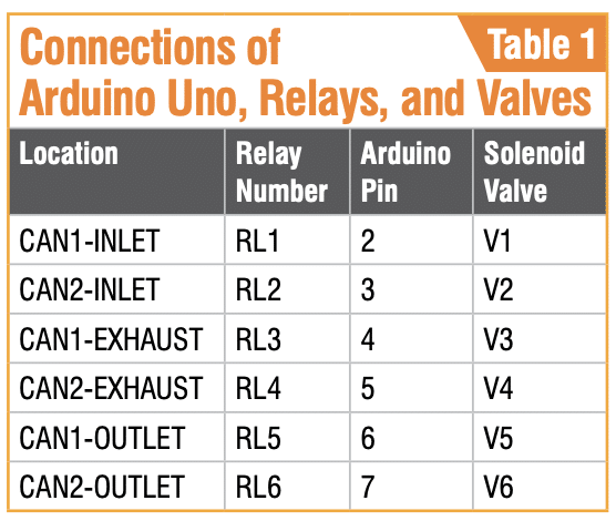
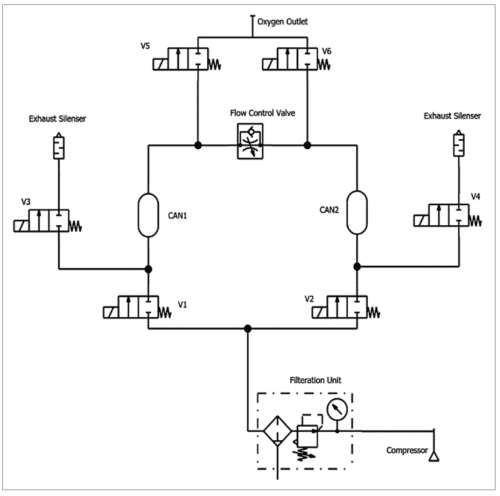
For better understanding valves’ (V1 through V6) and relays’ (RL1 through RL6) functioning associated with the project, please refer Table 1. Here, the two canisters are CAN1 and CAN2. The functional block diagram of CAN1 and CAN2 are shown in Fig. 3. The pneumatic arrangement is shown in Fig. 4.
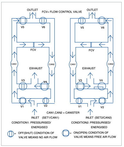
Working of the circuit is simple. First, you need to upload the source code to Arduino and connect the power supply. Relays RL1 through RL6 energise and de-energise according to the software. In the prototype, relays RL1, RL4, and RL5 energised for 40 seconds and relays RL2, RL3, and RL6 de-energised for 40 seconds to open and close the solenoid valves, respectively. Thereafter, the cycle repeats. You can see their status on the serial monitor of Arduino IDE as below:
- Set 2 Pressurised
- Set 1 Exhausting
- Set 1 Pressurised
- Set 2 Exhausting


