


 This Smart SOS Device is a wearable safety and alarm device that can be operated easily, especially by children and senior citizens when in distress. It may come in handy as the world is constantly witnessing an increase in the number of criminal activities. Senior citizens living alone are vulnerable to panic situations due to safety reasons or, sometimes, a medical condition.
This device can send an SOS call and simultaneously raise an alert alarm if needed.

The device is most often used for emergency alert notifications. It is a discreet device that lets the user send an SOS alert to quickly communicate for help from a trusted person by using GSM, GPS, or GPRS. It is used especially for anti-aggression alarms in jewelry stores, banks, or small businesses, and for personal safety.
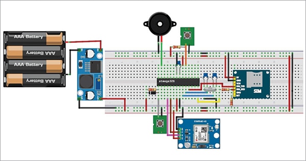
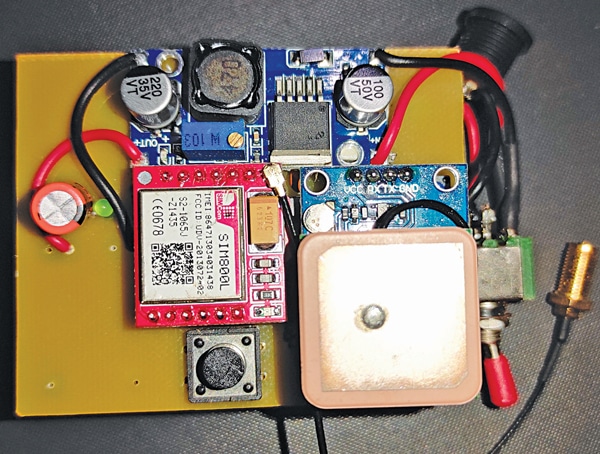
In this project, we aim to build a customized, cost-efficient version of the SOS button, which is stealthy and uses the best-in-class GSM-GPS modules along with a high-decibel buzzer. Its hardware interfacing on the breadboard is shown in Fig. 1.
Smart SOS Device Circuit
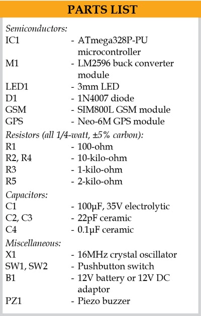
The components used in the project and their function are described below.
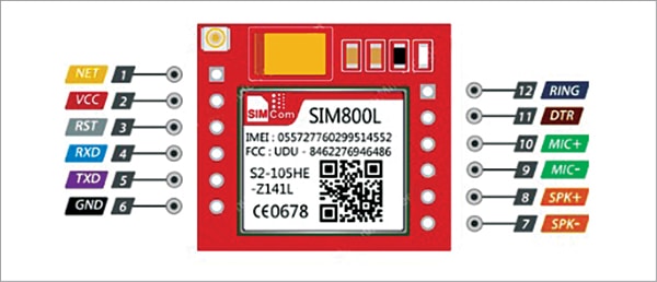
SIM800L is a miniature cellular module that allows GPRS transmission (sending and receiving), SMS, and voice calls. It is a low-cost device with a small footprint and quad-band frequency. The module is a perfect solution for any project that requires long-range connectivity. Pin details of SIM800L are shown in Fig. 2.
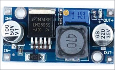
Buck Converter (or step-down converter) is a DC-to-DC power converter, which steps down voltage (while stepping up current) from its input (supply) to its output (load). A DC-DC step-down converter basically converts a higher input voltage to a lower output voltage by ‘chopping’ it up by rapidly switching the output power. The buck converter module is shown in Fig. 3.
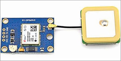
Neo-6M GPS module is a well-performing complete GPS receiver with a built-in 25x25x4mm ceramic antenna, which provides a strong satellite search capability. With the power and signal indicators, the status of the module can be monitored. The GPS module is shown in Fig. 4.
ATmega328P is the microcontroller used in an Arduino board. After uploading the code into this microcontroller using an Arduino board, it can be plugged out and used in the breadboard prototype.
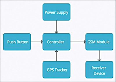
As shown in the block diagram (Fig. 5), there are also some other components like push buttons (SW1 and SW2), GPS module, GSM module, and power supply. The circuit diagram of the project is shown in Fig. 6. The microcontroller is, of course, the heart of the project.
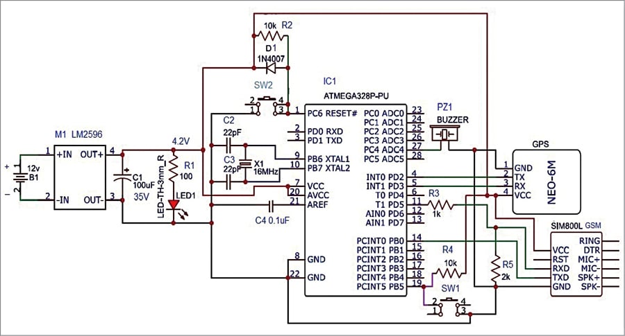
Whenever the push button SW1 is pressed by the caller, the microcontroller gives the information about the caller, like his/her location and emergency SMS, to the registered number in the GSM module. As a result, the receiver mobile receives the caller’s SOS message.
As shown in the circuit diagram, the push button SW2 is used to reset the circuit (whenever there is something wrong in the program). LED1 is used to indicate the presence of power in the circuit. The circuit can be powered by a 4.2V supply from the converter LM2596 module.
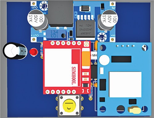
A 3D view of the prototype generated by the software is shown in Fig. 7 and the author’s prototype is shown in Fig. 8.
Software
Arduino IDE 1.8.15 is used to write, compile, and upload the code (smart_SOS_final.ino) into the Arduino board. The code requires a TinyGPS++.h header file.
Download Header File
Before uploading the code, enter a valid 10-digit phone number in the code
String number = “xxxxxxxxxx”;
where ‘xxxxxxxxxx’ is the phone number to receive the SOS message in the receiver’s mobile phone.
Download Source Code
Construction and Testing
EasyEDA is a free web-based EDA (electronics design automation) tool, which gives the facility to design schematic diagrams as well as PCB layouts. After completing the schematic diagram on the EasyEDA platform, select Design>Convert schematic to PCB. Adjust all the components of the circuit in the best minimum space. Then select Route>Auto route.
EasyEDA can generate 2D and 3D visualizations of the PCB. To get them, select 2D View and 3D View, respectively. The 3D view is shown in Fig. 7.
Assemble the circuit on a breadboard or PCB. Insert the SIM card in the slot of the GSM module. When SW1 is pressed, GSM calls the mobile number already entered in the program code, and the buzzer sounds. The buzzer sound is to alert nearby people.
Once the call is established, GPS gets latitude, longitude, and altitude coordinates and thus collects the exact location of the caller. The link to this location is sent to the receiver’s mobile phone along with the recorded SMS message. On opening the received link, the receiver gets to know the exact location of the caller on Google Maps.
Learn how to send SMS using GSM Module.
If you face any issues while making this project, please feel free to ask in the comments below.
Kamlesh Vasoya is an electronics hobbyist

Hi Kamlesh, I want to construct also a similar project. But I have a problem with the GMS module SIM 800L which does not connect to any network. I have inserted the SIM of BSNL (ACTIVE 2G) but the AT command shows the SIM number through Serial Monitor. but No Network pls. Pls contact me on my mail [email protected]. Thanks in Advance.
dear sir
can i add one another number in this system i change String number1 = “xxxxxxxxxx”; and String number2 = “xxxxxxxxxx”; also changes in message as number 1 and number 2 but it show code ok but when i put in arduino message goes only one number please help me sir i am using smd arduino board