


Each device connected to the I2C bus is software addressable by a unique address. The device that controls the sending and receiving of messages by controlling the bus access is referred to as the master and the devices that are controlled by the master are referred as slaves. Both the master and the slaves can transmit and receive messages. It is a synchronous protocol that allows a master device to initiate communication with a slave device. The master device controls the SCL, which dictates the timings of all transfers on the I2C bus.
The I²C protocol comprises a set of conditions to establish communication between the devices. These include:
1. Start condition
2. Sending of the slave address along with read/write information by the master
3. Acknowledgement by the slave device
4. Data transmission between the master and the slave device
5. Stop condition
Prior to any transmission, a start condition needs to be issued on the bus. The start condition acts as a signal to all connected ICs that something is about to be transmitted on the bus. It is initiated by the master by sending a high-to-low transition on the SDA line whilst SCL is high (Fig. 2).

After the start condition, the 7-bit slave address followed by the eighth bit is sent on the SDA line by the master, where a ‘0’ on bit indicates a write operation from the master to the slave (master is the transmitter and slave is the receiver) and a ‘1’ indicates a read operation from the slave to the master (master is the receiver and slave is the transmitter). The MSB of the address bits is sent first followed by the other bits. The value on the SDA line can be changed when SCL line is low.
The slave device whose address is the same as the address being sent out by the master responds with an acknowledgement bit on the SDA line by pulling the SDA line low during the ninth clock cycle of the SCL line. After that, the transmission takes place between the master and the slave. Each byte on the SDA line for transmission is 8 bits long with the MSB being sent first. Also, the SDA line must not be changed when SCL line is high, except for the start and the stop conditions. Any number of bytes can be transmitted, however each byte is to be followed by an acknowledgement bit. Fig. 3 shows the transmission process.
To signal the end of data transfer, the master sends a stop condition by pulling the SDA line from low to high whilst the SCL line is at high (Fig. 4).
I²C master controller implementation
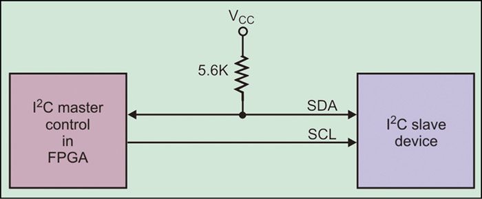
In this section, the implementation of the I²C master controller using an FPGA is discussed. Any FPGA can be chosen as per the designers’ requirement. Fig. 5 shows the interconnection between the FPGA and the slave device. As one can see, there are two lines required for connecting the master and the slave devices in an I2C protocol. Multiple slave devices can be connected using the same two lines.
Download Source Code: click here
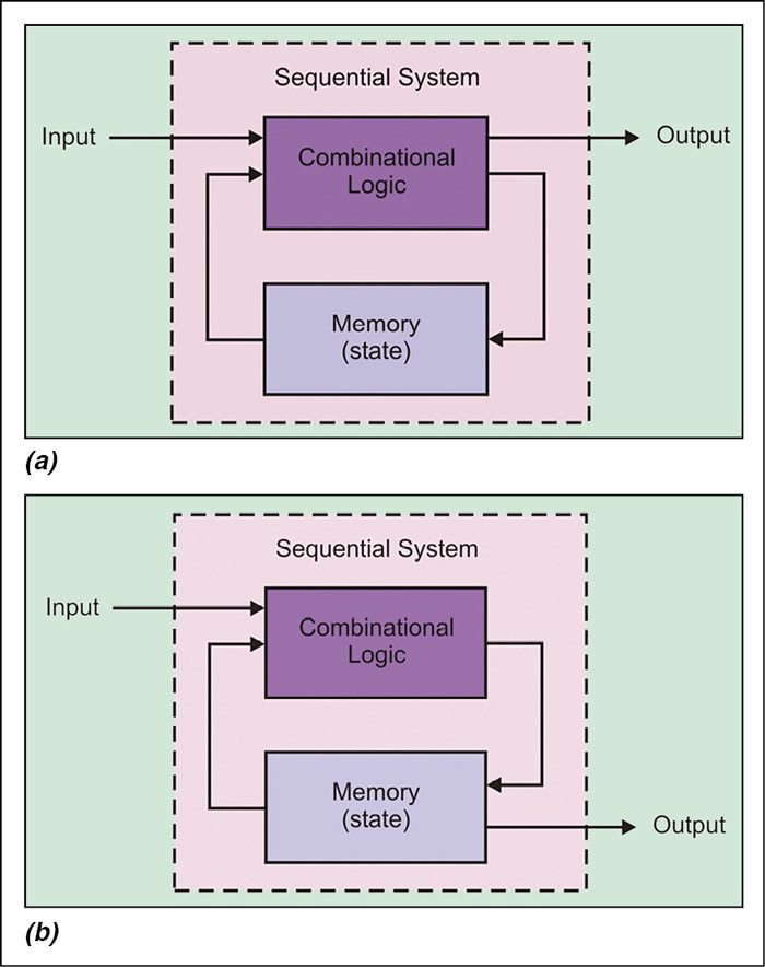
I²C master controller in an FPGA will be implemented using a finite state machine (FSM). Any controller can be implemented using an FSM, which is a mathematical model of computation used to design both computer programs and sequential logic circuits. FSM is conceived as an abstract machine that can be used in one of a finite number of states. It can change from one state to another when initiated by a triggering event or condition referred to as transition. FSMs can be classified as Mealy FSM and Moore FSM. In a Mealy FSM, the output depends on the current input and the current state (Fig. 6 (a)) whereas in a Moore FSM, the output depends on the current state only (Fig. 6 (b)).

Why do the state seem to be random numbers? Also, why use such a large data type for the states if only 17 states are required?