


The development of modern electronic modules requires even more appropriate tools to facilitate their early prototyping. Mixed Analog/Digital systems today need simulation platforms based on co-simulation between different analog and digital simulations tools, falling in a higher cost and slower computation times, due to the need of a continuous data transfer among them.
In this article, an analog-digital mixed signal modeling approach based on the conversion of analog Matlab/Simulink model to C code is presented, along with a real case study.
Goal of this approach is to create an interactive simulator, operating-system independent, able to run time-effective Mixed A/D Signal simulations.

The integration of the C code (for analog modules) with the VHDL/Verilog code (for the digital cores) eliminates the need of co-simulation, thus reducing model complexity, cost and improving the code portability.
In the present work the model of a complete Light Emitting Diodes (LED) driver module is reproduced. Its analog parts were originally modelled in Matlab/Simulink while the Digital core was represented by mean of its related VHDL code. The model of an external Serial Peripheral Interface (SPI) module was also implemented in order to send digital command to the driver and so to simulate the control performed by a virtual Microcontroller.

All this has been achieved realizing an ‘interactive’ user-friendly web Graphic User Interface (GUI), thus enabling to change several system parameters and to modify the devices setting while a simulation is running. Definitively, the tool works just like a ‘live datasheet’ allowing to analyze the device model in dynamic conditions, along with variation of inputs and digital command sent by the virtual Microcontroller. It can be massively used for customers support, marketing activities, load compatibility definition and design support. In the specific case, the final generated Digital Code was built for Modelsim and then successfully tested with NCSim, in order to prove the independence of the approach from the digital simulator.
Introduction
Mixed mode A/D models can be simulated in Matlab or Simulink environments with the support of the EDA Simulator Link that provides a co-simulation interface with commercial HDL simulators from Mentor Graphics, Cadence, and Synopsys. Matlab code or Simulink models can also be used as a test bench for the generation of stimulus for HDL modules provided by designers and for analyzing the simulation’s results. Communication interface may be bidirectional and Matlab/Simulink-HDL modules can be connected in closed loop.
In this way, any mixed A/D model can be virtually simulated, developing models of analog parts and interfacing them with the HDL modules for the digital parts (Fig. 1).
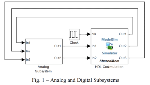
The advantage of this solution is a high flexibility in the projecting phase. On the other side, full simulation environment, consisting on Matlab/Simulink + Toolbox (at least EDA Simulator Link) and a compatible HDL simulator, must be available for third party users. One way to drastically reduce cost and complexity for using the above tools is to compile analog Simulink parts and integrate them in HDL simulator.
For a given A/D system, the proposed modeling workflow is the following:
- Build the behavioral Simulink models of each analog model (granularity is up to the purposes)
- Integrate in the Simulink environment the Digital part (Native VHDL/Verilog) by means of EDA Simulator Link (Co-simulation Simulink/HDL Simulator).
- Generate standalone C code via Simulink coder for the analog subsystem only.
- Modify generated code to integrate it with VHDL or Verilog foreign C interface (so obtaining a separate library)
- Write HDL wrappers for the C analog generated library and top module.
- The final model requires only a HDL simulator to run (e.g. Modelsim or NCSim).
Foreign VHDL/Verilog C Interfaces
Modern HDL simulators can integrate foreign language codes (e.g. C/C++) for behavioral modules descriptions via external interfaces. Moreover it is possible to implement C subroutines inside VHDL architectures and integrate them with Verilog modules or vice versa.
VHDL C interface is commonly referred as Foreign Language Interface (FLI) or VHDL Procedural interface (VHPI); FLI and VHPI implementations depend by HDL simulators and are usually described in their own reference manuals. On the contrary, Verilog Programming Language Interface (PLI) is a standard procedural interface and is described by IEEE 1364-2005 Language Reference Manual and many third part ones.
From Simulink to C Code Conversion
Simulink Coder (formerly Real-Time Workshop) is an application of Mathworks which generates and executes C and C++ code from Simulink diagrams, Stateflow charts, and MATLAB functions.
It automatically builds modules that execute in Real-Time or Stand-alone non-real-time simulation for most Simulink blocks and many MathWorks products (Fig. 2).
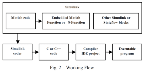
The generated source code matches the functionality behavior of original MATLAB/Simulink one with high degree of fidelity.
Selecting ‘Generic Real-Time target’ (grt) option in ‘Code Generation’ pane, once the code generation is complete, several C/C++ files are generated in the ‘X_grt_rtw’ directory (where ‘X’ is the model name). Number and size of generated files depend on the model complexity.‘X.c’ is the stand alone C code that implements the model.
Other files from Matlab installation path are also used for code generation and execution.
In particular, the file ‘grt_main.c’ contains the main C routine used to initialize all the variables, to allocate memory, invoke the functional routine that implements the model and terminate the program.
In order to simplify the above procedure, selecting ‘Create Visual C/C++ Solution File for the grt target’ a project file referring all required C/C++ files and settings is generated and ready to be imported in Visual Studio.
ModelSim Language Interface
In order to interface the generated code with VHDL, Visual Studio project and ‘grt_main.c’ file need to be modified, according to Modelsim FLI specifications.
Before starting to create a FLI application, the following additional concepts have to be better cleared.
A foreign VHDL architecture is a design unit that is instantiated in a design but that does not (generally) contain any VHDL code. More likely it is a link to a C model that can communicate with the rest of the design through the ports of the foreign architecture.
FLI routines are C functions providing procedural access to information within Model Technology’s HDL simulator, like Modelsim. A user-written application can use these functions to traverse the hierarchy of an HDL design, get information about and set the values of VHDL objects in the design, get information about a simulation and control a simulation run. The header file, ‘mti.h’ implements all functions and types that can be used by FLI applications and must be included in the modified ‘grt_main.c’.
When the simulator starts, it first goes through an elaboration phase during which the entire design is loaded, connected and initial values are set. During this phase, all foreign shared libraries are loaded and the initialization functions of all foreign architectures are executed.
The simulation phase begins when the first run command is executed and continues until a quit or restart command is executed. When a restart command is executed, the simulator goes through its elaboration phase again.
To use the foreign language interface with C models, VHDL architecture must be first created and compiled with the suited FOREIGN attribute containing the name of the initialization function (‘app_init’) and the path of the shared object file to be loaded (‘app.so’).
The 1st step from the C side for modelsim FLI is to modify configuration parameters in Visual Studio project, according to the following steps:
- Change configuration type to ‘Dynamic library (.dll)’
- In C/C++\general pane, add ‘\include’ to ‘Additional include directories’.
- In linker\general pane, set output file to ‘app.so’
- In linker\Input pane, add ‘\win32\mtipli.lib’ to ‘Additional dependencies’.
- In linker\command line pane, add: ‘-export: app_init’ to ‘Additional options’.
The next step is to modify the main function in ‘grt_main.c’, according to the declaration of an initialization FLI function.
The drawback of this solution is that it uses functions of a specific proprietary (Mentor, Cadence, Synopsys…) and then it is suitable only for that proprietary. In order to simulate the same system with another digital simulator, it is required to write a different FLI or VHPI, based on simulator reference (due to a lack of FLI/VHPI standardization). In the following, an alternative solution based on verilog PLI, that is suitable for almost every digital simulator.
The 1st step from the C side for PLI is to modify configuration parameters in Visual Studio project, according to the following steps:
- Change configuration type to ‘Dynamic library (.dll)’
- In linker\general pane, set output file to ‘app_vpi.sl’
- In linker\command line pane, add: ‘-export:vlog_startup_routines’ to ‘Additional options’.
The second step is to write a C language ‘calltf’ routine that will be called when the Verilog simulator executes the ‘$app_vpi’ system task.
The third step in creating a new PLI application is to notify the Verilog simulator about the new system task or system function name and the C routines which are associated with the application (‘register’ routine).
Optionally a ‘compiletf’ routine can be defined to verify that the system task or system function is being used correctly and has the correct types of arguments.
Finally, the ‘app_interface’ routine (defined in ‘calltf’) reads the inputs, calls the C model ‘rt_onestep’ included in ‘grt_main.c’ and writes outputs to Verilog signals.
Test Case
The above presented procedure has been adopted for developing a simulation environment including STMicroelectronics Intelligent Power and Smart Power models devices for automotive applications. In the specific test case, the application schematic of a LEDs driver L99LD01 has been reproduced, including the external circuitry (Fig. 3).
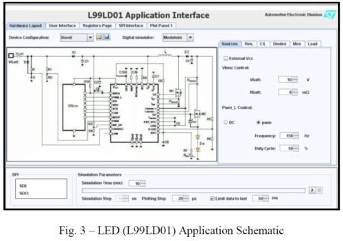
Initially, the entire simulation schematic was developed in Matlab/Simulink (+SimPowerSystems+ EDA Simulator Link). The digital core was co-simulated by Modelsim.
In a further step, the related C Code has been generated by means of Simulink Coder and compiled. At the same time, a suitable PLI interface has been realized.PLI interface, initially designed for Modelsim environment was successfully tested with NCSim in Linux/Sun environment. Compared to VHPI, PLI revealed to be faster and less memory demanding; furthermore it is suitable for almost every digital simulator able to run mixed VHDL/Verilog simulations.
Real Time Interactive Web GUI
Thanks to the PLI interface, final version of the simulator can be compiled in both Modelsim and NCSim environments.
To facilitate the usage of such simulator, a web GUI was developed, so allowing, independently from the adopted operating system, to use a digital simulator running on a server and to modify simulation parameter values in real time. At the end, the tool acts just like a ‘live datasheet’. Java language was used for the web GUI, this due to the possibility to use many functions for telnet, ssh or ftp. The only prerequisite for the end user is to eventually install the java run time environment, which is freely available for the most common operating systems.
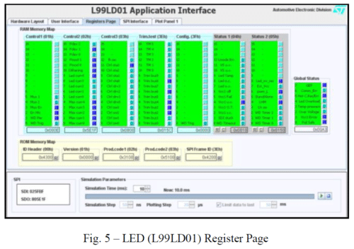
When the simulation starts, the web GUI connects to the server via ssh, checks for licenses and starts Modelsim or NCSim digital tool. Parameters are passed to the simulator by means of a text file via ftp. Every plotting step (e.g.20ms) simulator checks for parameters and plots values. The Registers Page of the user interface allows the user to act as a micro, giving the possibility to send and receive SPI commands, force some faults and see results in real time, in an explicit view (by means of colored flag) or in a more detailed view where every single register bit is showed (Fig. 4 and Fig. 5). When the simulation starts, the web GUI connects to the server via ssh, checks for licenses and starts Modelsim or NCSim digital tool. Parameters are passed to the simulator by means of a text file via ftp. Every plotting step (e.g.20ms) simulator checks for parameters and plots values. The Registers Page of the user interface allows the user to act as a micro, giving the possibility to send and receive SPI commands, force some faults and see results in real time, in an explicit view (by means of colored flag) or in a more detailed view where every single register bit is showed (Fig. 4 and Fig. 5).

For example, a Vcc1 under voltage fault is forced and a change in the LED Current set point value applied (Fig. 6).
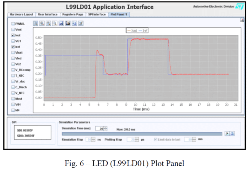
As consequence of the former action, some flags related to Vcc1 became red, thus indicating a warning or an error involving this parameter and the Global Error Flag (GEF) as well. The latter action leads to a SPI frame sending for every variation of the set point of the current flowing through the LEDs chain. In the picture both the current set point (in blue) and how the device is behaving (in red) are visible.
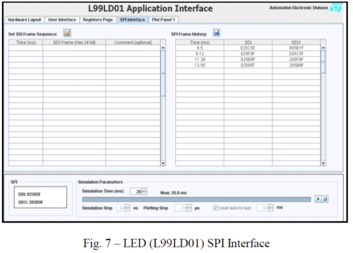
In another window (SPI Interface) all the SPI frames are recorded and a batch sequence of SPI frames can be programmed to be sent at specific time (Fig. 7).
Conclusion
A/D Mixed mode simulation was done for commercial STMicroelectronics L99LD01 High Efficiency Constant Current LED Driver, converting Simulink analog parts to C and interfacing them to digital simulator via VHDL/Verilog foreign C architecture. With this unique mixed-signal simulation environment, based only on Modelsim or NCSim digital tools, users are able to simulate A/D mixed models.
A solution for complete standalone environment is under evaluation. To do this, in addition to the analog part model conversion into a Code (ex. C/C++), able to be compiled and made executable in a standalone file, VHDL/Verilog code conversion is required as well, in the same language. At present the L99LD01 digital code has been manually converted into an embedded Matlab function, from this to C code and then integrated with the C code related to the analog parts. The conversion of VHDL/Verilog code is the real bottle neck of the entire process. An automatic tool could represent a huge improvement in the direction of developing A/D mixed mode simulators in standalone format.
References
[1] Matlab, Simulink and Simulink Coder manuals
[2] Modelsim SE Foreign Language Interface manual – Version 6.4
[3] 1364-2005 IEEE Standard for Verilog Hardware Description Language
[4] The Verilog PLI Handbook, Stuart Sutherland, Sutherland HDL, Inc. (partially available on Google book)
[5] Modelsim VHPI/pli/vpi examples
[6] Mixed-signal modeling using Simulink based-C, Shoufeng Mu – Michael Laisne, Qualcomm Inc
[7] Java – Netbeans user guide


Good way of telling, and fastidious paragraph to obtain facts regarding my presentation subject, which i
am going to deliver in academy.
Fastidious response in return of this difficulty
with real arguments and explaining all concerning that.