


The oil in lamps that are traditionally lit in a pooja room has to be topped up from time to time. The solar lamp described here can provide light nonstop for many years without any intervention.
In this system, a small solar photovoltaic (PV) panel turns on the LEDs during the daytime and charges two supercapacitors during the day. In the evening, when the daytime LEDs turn off, another set of LEDs (joule thief) is turned on using energy stored in the supercapacitors.
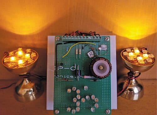
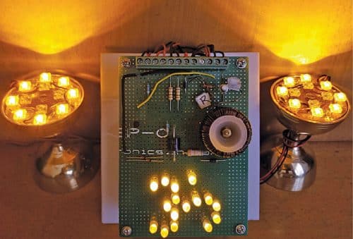
As supercapacitors can be charged and discharged any number of times, the whole system can work nonstop for 15 years or more. The author’s prototype with joule thief LEDs on is shown in Fig. 1.

Circuit and working
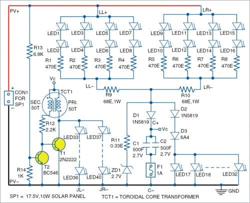
The circuit diagram of solar pooja lamp using LEDs is shown in Fig. 2. The complete system comprises solar lamp LEDs, a supercapacitor charging circuit, and joule thief circuit.
The solar daylamp uses a 10W-peak solar PV panel whose specifications are:
Voltage at maximum power (Vmp) = 17.5V
Current at maximum power (Imp) = 0.58A
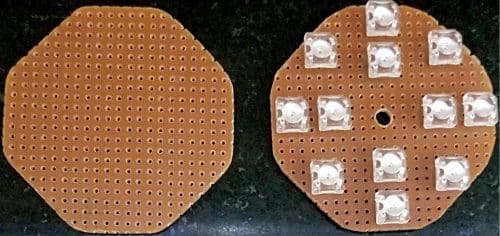
The daylamp has two arrays of eight connected yellow high-brightness LEDs each. These LEDs (LED1 through LED16) are assembled on two octagonal PCBs as shown in Fig. 3.
LED1 through LED8 are soldered on left side lamp (LL) PCB and LED9 through LED16 are soldered on right side lamp (LR) PCB. The respective current-limiting resistors R1 through R8 are also mounted on these PCBs. The PCBs can be mounted on a brass lamp that is easily available in the market.
The positive connections from these PCBs are labelled as LL+ and LR+ for left and right lamps, respectively. The negative terminals LL- and LR- are connected to resistors R9 and R10, respectively. The sum of current flowing through R9 and R10 is used to charge supercapacitors C1 and C2. Diode D1 prevents discharge of capacitors when PV voltage is not present. For safety, fuse F is included in series with the negative terminals of C1 and C2.
Calculation of current limiting resistors:
Forward drop of yellow LED (Vf) =2V
Max forward current of LED (If) =20mA
Total current from one lamp (4-LED array)=4xIf=4x20x10-3= 0.08A
Value of current limiting resistance =(18.5 – 2 x Vf)/0.08=181.25Ω
Equivalent value of resistances R1 through R4=470/4=117.5Ω
Value of R9=181.25 – 117.5= 63.75Ω (standard value of 68Ω is chosen)
Please note:
- Higher value of PV voltage of 18.5V has been considered for the worst case scenario.
- LED current is maximum when capacitors are fully discharged.
- Resistors R1 through R8 balance the current flowing through the LED arrays.
Supercapacitor charging circuit
As mentioned earlier, the current flowing through day lamps LL and LR is used to charge capacitors C1 and C2. The charging current calculations are:
Charge required to charge capacitors to 2.5V (Q)=CV=1000×2.5= 2500 Coulombs
Total average charging current from R9 and R10 (Ic)=0.1A (assumed)
Time required for charging=Q/Ic=2500/0.1=25000 seconds or 7 hours (approx.)
Note. The charging current varies from 0.16A to 0.06A, depending on the PV voltage (Vpv) and capacitor voltage, etc. Above calculation assumes an average current of 0.1A to get fair idea about charging time.
It is important to limit the capacitor voltage to less than the rated value. C1 and C2 are rated for 2.7V. Keeping some safety margin, we limit the voltage to 2.5V.
At the anode end of diode D1, the circuit comprising diodes D2, D3, and 16 LEDs (LED17 through LED32) is connected. The LEDs are all connected in parallel to form the ‘om’ sign (a spiritual Devanagari ॐ symbol).
The forward drop of a yellow LED is 2V and forward drop of diode D3 is 0.7V. Therefore, this branch limits the voltage at anode of D1 to 2.7V. Diode D3 has been selected to be of high current rating of 6A. Even though charging current is 0.16A, high current rated diode provides a stable forward drop of 0.7V at all charging current values.
LED17 through LED32 remain off till the capacitor voltage builds up to 2V. After that, these LEDs start turning on slowly. Because, as the capacitor charging current reduces, it gets diverted to these 16 LEDs. When these 16 LEDs are fully on, it means the capacitors have been charged to 2.5V.
In order to ensure that the capacitors do not charge beyond 2.7V, the redundant circuit comprising Zener diode ZD1 and resistor R11 has been provided. Value of R11 has been chosen such that the capacitor voltage does not exceed 2.7V.
Joule thief circuit
The supercapacitors thus charged are used to turn on the joule thief LEDs (LED33 through LED40) once the sun sets. If we directly connect LEDs to the supercapacitor, the LEDs will be on till the capacitor voltage drops to 2V (Vf). After that, the stored energy remains unused.
Joule thief is a popular circuit that is used for extracting the remaining energy from used primary batteries. Here, it is used to extract stored energy from the supercapacitors. Joule thief is a self-oscillating voltage booster circuit.
The Joule thief circuit here consists of NPN transistor T1 and ferrite-core transformer TCT1. The primary coil of the transformer is connected between capacitor voltage Vc and collector of transistor T1. Its secondary coil is connected to the base of T1 through current-limiting resistor R12.
Initially, with T1 switched on, current builds up in the primary coil of transformer and induces voltage in the secondary coil. The secondary coil drives the transistor to deep saturation. Once the current has built up in the primary, the current stops increasing.
When there is no change of current occurring in the primary, there is no voltage induced in the secondary. This turns off T1. The stored energy in the primary produces a large voltage spike and the eight LEDs (LED33 through LED40) connected to the collector of T1 turn on.
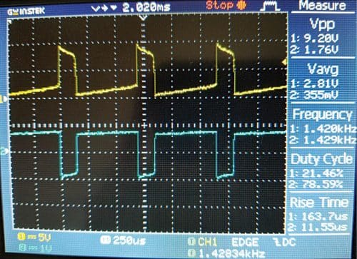
Once the stored energy in the primary is transferred to the LEDs, the transistor again turns on and the cycle repeats. Joule thief waveforms are shown in Fig. 4.
The eight LEDs that are powered using joule thief circuit are soldered on the octagonal PCB as shown in Fig. 3. LED33 through LED36 are soldered in series forming the inner circle LEDs on the left-side octagonal PCB and LED37 through LED40 are soldered in series on the right-side octagonal PCB.
Transistor T2 is used to sense the presence of voltage Vpv. Throughout the day, PV voltage is available and T2 is on. The collector of T2 is connected to base of T1. When T2 is on, the base of T1 is clamped to zero voltage. In the evening, when base voltage of T2 becomes <0.6V, T2 turns off and joule thief circuit starts working and keeps the LEDs on through the night. Next morning, when PV voltage builds up, T2 turns on and joule thief circuit turns off. By then, the daylamp would have turned on. Thus, the proposed pooja lamp circuit provides light without interruption.
The supercapacitors can be charged and discharged thousands of times, hence the circuit is likely to work for more than 15 years without any degradation in performance.
Construction and testing
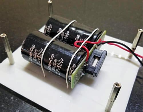
The two supercapacitors C1 and C2 are mounted on a plastic base and connected in parallel as shown in Fig. 5. Fuse F1 is mounted on the PCB. Four standoffs are provided on the plastic base for mounting the main PCB.
Photograph of the main PCB is shown in Fig. 6. A 12-pin terminal connector is provided at the top edge of the PCB for all external connections. The capacitor charging circuit and the joule thief circuit are assembled on this PCB. LED17 through LED32 are also mounted on this PCB in the shape of ‘Om.’
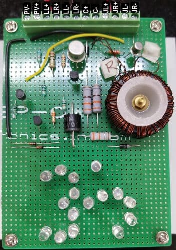
Fig. 7 shows pooja lamp with day lamp LEDs on. LED17 through LED32 are also on, which indicates that the capacitors are being charged. Fig.1 shows pooja lamp with joule thief LEDs turned on during night when PV voltage becomes zero. These lamps remain on throughout the night.
Also check: Improved Pooja Lamp is proposed with 32 extra LEDs (5 mm 20 mA) to get more light in the day time. Further, clock power supply circuit is integrated, which drives two wall clocks. The power supply circuit draws power from the same PV panel used for Pooja Lamp.
Check these 10 solar electronics projects you can build at home.
Dr Vijay Deshpande recently retired from Honeywell India and is now working on solar energy projects. He has worked for more than 30 years as an electronics hardware engineer in several companies
