


 Although 60/40 solders melt at about 200°C, the tip temperature of a soldering iron should be about 370°C. This is necessary to make a good joint quickly without the risk of overheating delicate components. One should not hold the tip of the iron to the joint for too long at such high temperature.
Unfortunately, at this temperature, the tip oxidises rapidly, requiring constant cleaning. That’s where this circuit can help as it keeps the soldering tip to just below 200°C while the iron is at rest. Oxidisation is then negligible and the iron can be brought back to soldering temperature in just a few seconds when needed. In addition, during normal soldering operation, where the iron returns to rest only momentarily, the tip temperature is unaffected because of the thermal inertia of iron.

Circuit and working
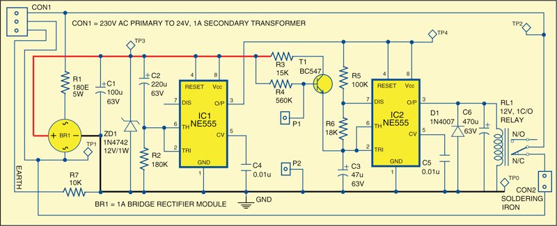
Fig. 1 shows the circuit of soldering iron tip preserver. Two 555 timers (IC1 and IC2) are the heart of the circuit. IC1 is wired in monostable configuration and provides an initial warm-up time of about 45 seconds to bring the iron up to the required soldering temperature. At the end of this period, its output pin (3) becomes high, enabling IC2 (wired in astable configuration) to switch the iron on via relay RL1. Here it gets heated for one second in every six seconds. This duty cycle is decided by R5, R6 and C3 when the iron is in the stand. The presence of the iron in its stand is sensed by electrical contacts P1 and P2.
When the iron is at rest, the base of T1 is pulled low and therefore T1 doesn’t conduct. Conversely, when the iron is out of its stand, T1 conducts to pull pins 2 and 6 of IC2 high, inhibiting its operation. During this time, pin 3 of IC2 is low and therefore the iron is continuously powered via normally-closed (N/C) contact of relay RL1.
Construction and testing
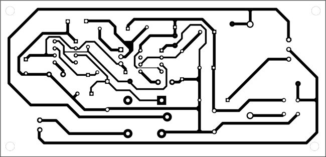
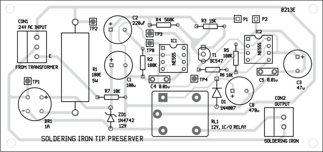
A single-side PCB for the soldering iron tip preserver is shown in Fig. 2 and its component layout in Fig. 3. Assemble the circuit on a PCB to minimise time and assembly errors. Carefully assemble the components and check for any overlooked error. Suitable connectors are available on the PCB to connect the secondary winding of the transformer and the soldering iron. Some slight modification of the stand may be required to sense the presence of iron in the stand. The warm-up time and standby temperature can be varied by changing the values of resistors R2 and R5.
Download PCB and component layout PDFs: click here
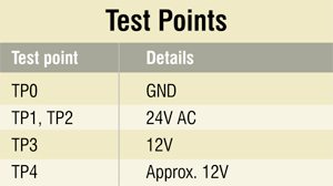
To test the circuit for proper functioning, check test points TP1 and TP2 for correct power supply to the soldering iron. These should be at around 24V. Check TP3 for power supply to timers as mentioned in the table. The output of IC1 can be checked at TP4.
For more exciting circuit articles: click here
The author is a regular contributor to EFY
In the DIY section Soldering Iron Tip preserver by Raj K. Gorkhali February 1, 2013 is nice. But I cannot understand the purpose of using R7(10k) between Earth and GND. Is there any terminological difference between Earth and GND? Please help me out if possible.
In the Soldering Iron Tip preserver circuit, a resistor R7 (10K) between the earth and ground is often used for safety and functionality reasons.Here are some reasons why a resistor is included in such a circuit:
1. The resistor helps to discharge any static electricity that might build up on the soldering iron tip. This is important in preventing damage to sensitive electronic components that you may be soldering. By providing a path for static discharge, the resistor helps protect both the soldering iron and the components being soldered.
2.Connecting the soldering iron tip to the ground (earth) helps to equalize potential differences and provides a safe path for current to flow in the event of a fault. This grounding helps protect the user and the equipment from electric shock.
3.It can act as a filter to prevent unwanted electrical signals from affecting the performance of the soldering iron or nearby electronic components.
4. Many electrical devices, including soldering irons, need to comply with safety standards that require proper grounding and ESD protection. The inclusion of a resistor in the grounding path can contribute to meeting these safety requirements.
5. It’s important to note that the specific design of a soldering iron control circuit can vary, and the resistor’s value may be chosen based on the requirements of the circuit and safety standards. Always follow the manufacturer’s recommendations and guidelines when working with soldering iron control circuits.
Regards