


 In India, we have a large power distribution system with heavy distribution losses and variations in industrial/ domestic load. This results in voltage variations that may damage electrical/ electronic appliances like light, fan, television, mixer-grinder, air-conditioner, heater, water pump, toaster, etc. Here, we describe how to make a solid state voltage stabiliser that does not use electro-mechanical relays and is suitable for most purposes. Key features of the solid-state voltage stabiliser are:
- Wide range of voltage variation from 120 V to 280 V
- Only two settings are required low voltage and high voltage
- Stabilised output of 220V
- Compact size
- Silent operation and no relay chattering sound
- Bar graph LED voltage indicator
- Low/high voltage indicator and cut-off protection
Block Diagram
The block diagram of a solid state voltage stabiliser is shown in Fig.1.
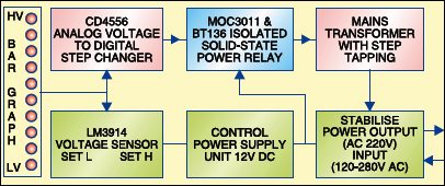
The circuit diagram comprises following four sections:

1. Analogue voltage to digital step changer
2. Isolated solid-state power relay
3. Control power supply unit
4. Mains transformer
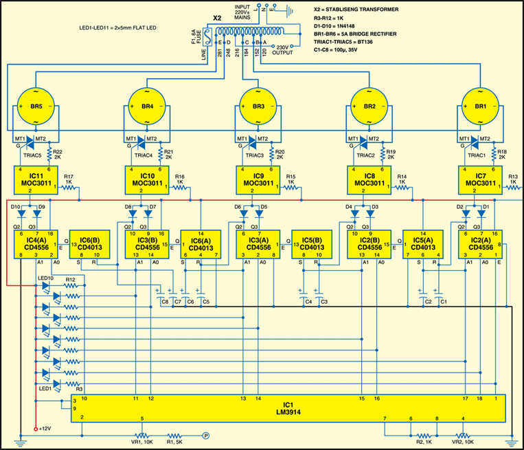
Analogue voltage to digital step changer
The circuit diagram of a solid state voltage stabiliser is shown in Fig.2. The heart of the stabiliser is IC1 (LM3914) bar display driver. It is used as LED type bar graph voltmeter with lower voltage and upper voltage settings through presets VR1 and VR2. IC1 senses mains voltage. The difference between the lower voltage and upper voltage is divided into 10 steps. every LED indicates one step or one voltage level and is lit depending on the level of voltage received.
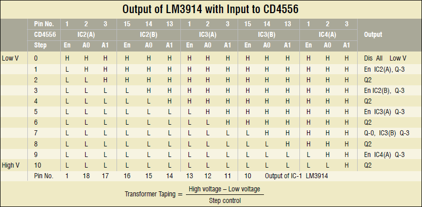
All the 10 outputs of IC1 that are used to lit the LEDs are also fed as inputs to dual decoder/demultiplexer CD4556. CD4556 is used for converting analogue voltage to digital steps to ensure that, at a given time, only one tapping of mains transformer gets input supply voltage from mains. In all conditions only one step can be active as per analogue input voltage.
Assume the first condition when the mains voltage is less than the lower set value. All the output pins (1, 18, 17, 16, 15, 14, 13, 12, 11, 10) of IC1 will be high. IC3(A) will be disabled and no step will be selected (means low volt 16, 15, 14, 13, 12, 11, 10) of IC1 will be high. IC3(A) will be disabled and no step will be selected (means low voltage cut-off).
Circuit operation
As the mains voltage increases to more than the lower set value, LED1 of the bar graph voltmeter glows as pin1 of IC1 is low and all other outputs pins are high. In this condition IC2(A) is enabled because input E (pin 1) is low. As inputs A0 and A1 of IC2(A) are high, out put Q3 goes low. This is step 1 of step charger.
When voltage increases, input A0 of IC2(A) goes low and its output Q2 also goes low. This is Step 2 of step changer.
Both these outputs are combined with 1N4148 diodes and given to cathode pin of internal LED of IC7 (MOC3011). As internal LED of IC7 glows, TRIAC1 conducts and provides AC mains to tapping ‘A’ of mains transformer X2.
When voltage increases further, both inputs A0 and A1 of IC2(A) go low, while both of its outputs go high , and TRIAC1 goes off. Input A1 and output Q2 of IC2(A) generate enable input E for IC2(B) with the help of set and reset input pins (S and R) of flip-flop IC5(A) (CD4013). Pin 1 of IC5(A) provides low signal to enable input E of IC2(B) and output Q3 of IC2(B) goes low. This is Step 3 of step changer. Similarly, other conditions work in the same manner (see Table).
The number of tappings for transformer X2 and the number of solid-stat relays to be used depend on the voltage range to be covered. If the minimum voltage can drop to 100 volts and the maximum could rise to 300 volts, we need to cover 200 volts deviation. This can be managed either through ten tappings with 20V difference or just five tappings with 40V difference between each.
Isolated solid state power relay
Isolated solid-state power relay comprises an opto-isolatortriac driver MOC3011, bridge rectifier (5A) and triac BT136. The opto-isolator triac driver MOC3011 is used for controlling the steps and connecting AC mains power supply to correct tapping of mains transformer X2 via solid-state relay. The capacity of solid-state relay depends on both the components traic and bridge rectifier. Here triac BT136 and 5A bridge rectifier are used for 1kW load. Triac BT139 with 10A bridge rectifier can be used for a solid state relay of more than 1 kVA and less than 3 kVA. You can use up to 3 kVA solid-state voltage stabiliser with 3 kVA transformer.
Control power supply
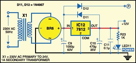
Circuit diagram of control supply circuit is shown in Fig. 3. The 230V, 50Hz AC mains is stepped down by transformer X1 to deliver a secondary output of 24V, 500 mA. The transformer output is rectified by full-wave rectifier BR6, filtered by capacitor C9 and regulated by IC 7812 (IC12), which provides a 12V DC output. C10 and C11 provide further filtering. LED1 acts as the power indicator. Resistor R23 acts as a current limiter.
When capacitors used in the output are more than 10 μF, it is necessary to protect the regulator IC using diode (in this case, D11), in case their input is short to ground. Unregulated DC supply voltage is used for input sensing by IC1 for controlling the steps of mains transformer through solid-state relays.
Mains transformer
The mains transformer used here is an auto-transformer with tappings of 120V, 152V, 184V, 216V, 248V and 281V, respectively (as shown in Fig. 2). All the tappings are connected with the voltage control solid-state relays to provide respective voltages. The tap at 216 volts is connected directly to the output.
Construction
A single-side PCB for the solid state voltage stabiliser is shown in Fig.4(View as PDF) and its component layout in Fig.5(View as PDF). The total circuit of solid-state voltage stabiliser can be assembled on a PCB. All the BT136 triacs need to be fixed on suitable heat-sinks with mica and insulated nut-bolts to isolate them. To begin with, the setting of solid-state voltage stabiliser is done without connecting mains transformer as described below.
Download PCB and component layout PDFs (Fig.4, 5): click here
1. Use a variable voltage transformer having 0 to 300 volts range and a digital voltmeter (3½-digit) for measurement of mains power supply.
2. Connect this solid-state voltage stabiliser with variable transformer starting from zero volts setting. Increase voltage slowly from 0 to 120 volts
3. Set variable voltage transformer output of 120 volts with the help of digital voltmeter
4. Set low voltage setting preset VR2 of IC-LM3914 so that only LED1 glows
5. Now set the transformer at 281 volts with the help of digital voltmeter
6. Set high voltage setting preset VR1 of IC1 so that all LEDs from LED1 through LED10 can glow
7. Set the transformer at 184 volts and check the LEDs
8. Set the transformer at 248 volts and check the LEDs
9. Move variable transformer from 120 to upside and check solid-state relay output one by one with the help of a test lamp of 220V, 40W. Also see table of CD4556.
10. Connect mains transformer tappings to solid-state relays with great care at proper tappings.
11. Now connect digital voltmeter to output socket and check the voltage with variable transformer from 120V ~ 281. the output should remain 220V
12. Connect test lamp as a load and check voltage variation. Now the solid-state voltage stabiliser is ready for use with a load of 1KVA.
EFY note
Male and female pin type power connectors may be used to connect mains transformer tapping with solid state relays on PCB. Bar graph LED voltmeter connection also provides male and female pin connection from PCB to front panel of the stabiliser.
The article was first published in January 2010 and has recently been updated.


It’s not running
Plz contact me early as possible
Kindly elaborate your query.
Traics and bridge rectifiers are burning can u have hardware of readymade project
Kindly elaborate your query.
Sir solid state voltage stabilizer is false project please dont put such a false project which is not working it creates nuissance to students
This is a fake project. The guy who says he made it and tested is lying. The basics of electronics is missing. How can on use a bridge rectifier like a relay? How does enabling the bridge rectifier turn on the transformer tapping? No wonder a lot of people are moving away from EFY. It was a good magazine back in the 90s but now it is not worth it.
HI Jagannath, thank you for pointing out the correction. I have escalated the issue to the concerned department.
so, fair to say this project/circuit doesn’t work AND has been dropped?