


 When this sound operated intruder alarm detects any sound, such as that created by opening of a door or inserting a key into the lock, it starts flashing a light as well as sounding an intermittent audio alarm to alert you of an intruder. Both, the light and the alarm are automatically turned off by the next sound pulse.
Sound Operated Intruder Alarm Circuit
230V AC mains is stepped down by transformer X1, rectified by diode D1 and filtered by capacitor C1 to give 12V DC. The voltage at the non-inverting input (pin 3) of op-amp CA3140 (IC1) is treated as the reference voltage and it can be set using preset VR1. The voltage at the inverting input (pin 2) is the same as that across the condenser microphone.
The condenser microphone should be carefully set for a high sensitivity of the sound. A high reference value means a subtle sound is enough to change the output of IC1 at pin 6. Fix the reference voltage such that the output remains unchanged during any false triggering.

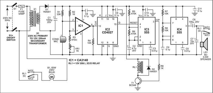
In the absence of any sound, the voltage at input pin 2 of IC1 is almost equal to the full DC voltage and therefore the output of IC1 remains low. Since IC CD4027 is wired in toggle mode, its output pin 15 is also low. This makes reset pin 4 of IC3 low to reset the astable multivibrator built around timer 555 (IC3). As a result, transistor T1 is cut-off and relay RL1 remains de-energised. In de-energised state, both the N/O contacts of relay RL1, i.e. RL1(a) and RL1(b), remain open. RL1(a) contacts keep the lamp turned off, whereas RL(b) contact disconnects the output of the astable multivibrator built around IC 555 (IC4) to disable the speaker.
Circuit operation
In the case of any noise, a current flows through the microphone and the voltage at pin 2 reduces to make the output of op-amp IC1 high. IC2 gets triggered by the pulse available at its pin 13 and its output at pin 15 goes high to enable astable multivibrator IC3. The output of IC3 goes high for three seconds and then goes low for 1.5 seconds. This repeats until pin 15 of IC2 remains high. The high output of IC3 energises the relay via driver transistor T1, while the low output de-energies the relay.
When relay RL1 is energised, relay contact RL1(a) passes on the AC power to bulb B1 and it lights up. At the same time, relay contact RL1(b) allows the output of astable multivibrator IC4 to the speaker and an audio tone is generated. The frequency of this audio tone is approximately 480 Hz. Both the flashing of the bulb and the audio tone continue as long as the output of flip-flop IC2 remains high.
Now if the circuit detects any further sound, the output of flip-flop IC2 goes low. This makes reset pin 4 of astable multivibrator IC3 low and IC3 stops oscillating. The low output of IC3 de-energises the relay to turn the bulb and the tone off.
The article was first published in December 2004 and has recently been updated.
