


 This speed indicator circuit is designed for indicating over-speed and direction of rotation of the motor used in mini hand tools, water pump motors, toys and other appliances.
Speed indicator circuit
A 12V DC motor (M1) is coupled to the rotating part of the appliance with a suitable fixing arrangement. When the motor rotates, it develops a voltage.
This speed indicator is built around operational amplifier CA3140 (IC1). Set the reference voltage (depending on the desired speed) by adjusting preset VR1 at pin 2 of IC1. When the voltage developed at pin 3 of IC1 is higher than the reference voltage at pin 2, output pin 6 of comparator IC1 goes high to sound piezobuzzer PZ1 and light up LED3.

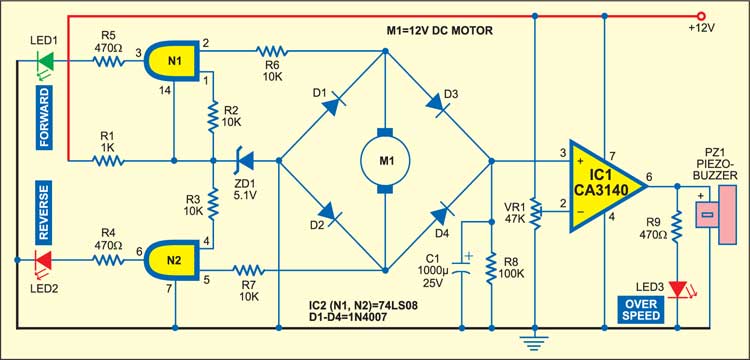
The rotation indicator circuit is built around AND gate 74LS08 (IC2). Pin 2 of gate N1 goes high when the motor rotates in forward direction, while pin 1 of gate N1 is pulled high via resistor R2. When both pins 1 and 2 are high, output pin 3 of gate N1 goes high to light up LED1. Similarly, pin 5 of gate N2 goes high when the motor rotates in reverse direction. When both pins 4 and 5 are high, output pin 6 of gate N2 goes high to light up LED2.
The article was first published in December 2005 and has recently been updated.

What are the applications of this project
I want overspeed indicator abstract and block diagram