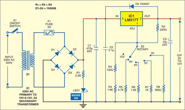
 This stabilized power supply circuit may be directly connected to 230V AC mains to derive output voltages of 3V to 12V DC for connection to the prototyping board.
Stabilized power supply circuit
230V AC mains input is down-converted to 15V AC by step-down transformer X1, whose secondary winding can support a current of 2 amperes. A bridge rectifier converts the AC to pulsating DC with a peak voltage level of 21V (15×1.4142). LED1 lights up to indicate the availability of output from the rectifier. Resistor R1 (2.2-kilo-ohm) limits the current through LED1 to a safe value below 10 mA. The output from the bridge rectifier is smoothed by 470µF capacitor C1. Capacitor C2 bypasses high frequency ripple.

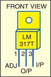
An adjustable, LM317T series 3-terminal, positive-voltage regulator is used at the output of the rectifier section for regulation. It is capable of supplying in excess of 1.5A over 1.2V to 37V output voltage range. However, here it has been used to supply discrete voltages in steps of 3V, 5V, 6V, 9V and 12V with the help of 5-way rotary switch S2, which brings in different resistor values between Adj pin of the regulator and ground, while R2 (between Adj pin and output pin) is a fixed resistor of 220 ohms. The output voltage (Vo) is given by the relation:
where ‘Rx’ is the resistance connected between Adj pin of the regulator and ground.
In 12V position (‘off’ position of the switch), the value of Rx is R3+R4=1900 ohms, while in various other positions it is the series equivalent of 1900 ohms in shunt with another resistance selected by the rotary switch. The table shows the equivalent series resistance in various positions of the rotary switch.

Note
X1 rating in the circuit diagram is wrongly printed. That is, 15V-0-15V should be read as 0-15V.
Discrete resistor (with 1% tolerance) switching is preferred to employment of a variable resistor because the wiper contact becomes erratic after some use and the tolerance (variation with temperature) of a variable resistor is also much higher.
Construction
The LM317T regulator is to be fitted with a heat-sink between the regulator and PCB to provide the best heat transfer. Note that the higher the load current or the lower the voltage across the load, the higher will be the heat dissipation at the regulator. Assuming that you adjust the output to 3V and the load draws a current of 1.5A, there is a voltage drop of approximately 10 volts across IC1. The power dissipation at IC1 is 10×1.5=15 watts. To dissipate this heat, you must use a heat-sink of 4×10cm size or so. A 3mm aluminium plate of the mentioned size screwed to the regulator will work efficiently. A minimum voltage differential of 3 to 4V between the input and output voltages is essential for proper regulation.

Switch S1, transformer X1, LED1, fuse F1 and rotary switch S2 are preferably mounted suitably in a metallic box. The heat-sink (aluminium sheet) is to be inserted flat between regulator and the PCB and secured using a nut and bolt after applying some heat-sink paste on the metal portion of LM317T. Use a rotary switch mounted on the box and extend the connections from the PCB to the rotary switch position with common connection going to the pole of the rotary switch. As LM317T has built-in short-circuit protection, no fuse at its output is necessary. The circuit should be wired using a proper PCB.
The article was first published in October 2007 and has recently been updated.


What should be the maximum capacitor value of output capacitor filter of Lm317 to get noise free output ?