


 Every microcontroller project needs a display. An LCD display with one or two rows for characters is a good choice but it needs several wire connections to make it work. There are seven segment LEDs which are either common-anode or common-cathode type. Earlier, these LEDs were used for number displays which had their pros and cons.
Proof of Concept Demo Video:
Suppose a 4-digit clock display is required, it needs four separate LEDs. These are wired in common for segments (cathodes) and the anode of each LED is separately excited, one after another, with a dwell time for each digit display of a few milliseconds in a multiplexed manner. Because of persistence of vision, the four LEDs appear as a continuous display, though they burn one after another.
Most projects use this method only for four or more digits for display. With eight wires to connect to segments (seven for the segments and one for decimal point) and four multiplexing anode signals to provide power supply one by one, totally 8+4+1=13 wire connections are needed for a 4-digit clock’s speed display. The last ‘1’ is for the common ground wire.
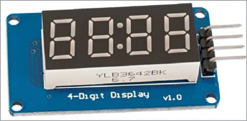
With the TM1637 LED module (Fig. 1) becoming easily available at an affordable price of around ₹90, projects of this kind have become extremely simple to construct. Using an Arduino Uno board, or even with a plain microcontroller chip, these projects are simple, quick, and easy to fabricate within limited cost. The simplicity lies in the fact that the TM1637 module comes with just four pins for connections. Out of the four, two are 5V and ground connections for power supply and the other two are for a two-wire (clock and data) interface like the so-called I2C bus which one can learn using the TM1637.
Illustrative example
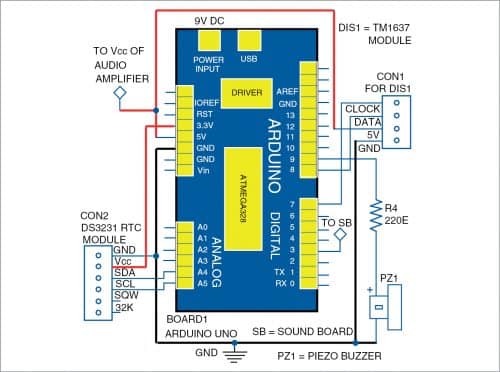
The TM1637 module’s data and clock pins are interfaced to the Arduino board through pins 8 and 7, respectively. Other than these two wires, 5V and ground wires are also connected to Arduino. The TM1637 module displays time with a central blinking colon.
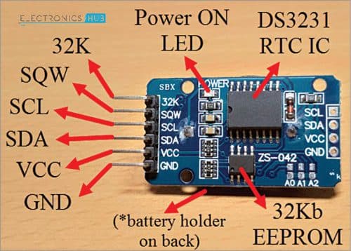
To get the real time, an easily-available DS3231 real-time clock (RTC) module is interfaced to the Arduino board. When switching on the circuit, the time shown is correct time that need not be corrected at all (except one time initial settings in the source code).
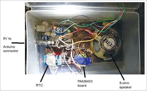
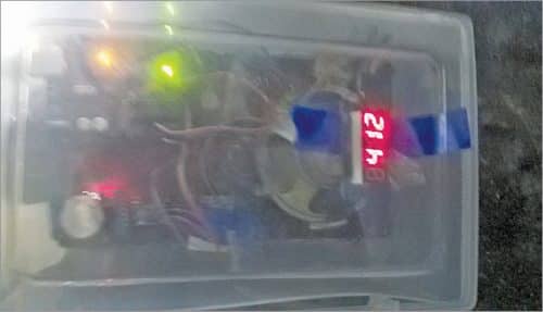
The RTC module also has just two wire connections. SCL and SDA pins of the RTC module are connected to A5 and A4 pins of Arduino board, respectively. The RTC has a 3V lithium round button cell battery like the one used in desktop computers. This fits on a round socket at the back of the module as shown in Fig. 4 and works for a year or more. Since the module has a battery, the real time is maintained even when the Arduino is off. Circuit diagram of talking alarm clock is shown in Fig. 3 and prototype setup is shown in Fig. 4.
The program needs talkie.h library file, which is available at this link. It includes the US English vocabulary. The library file must be included in libraries folder of Arduino IDE as well as the RTClib library as shown in Fig. 5.
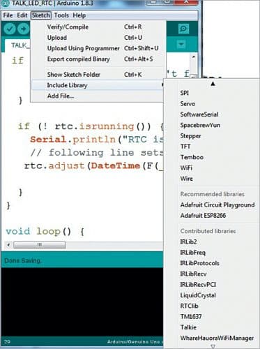
Go to Sketch/Include Library and search for the RTClib library to include it in the Arduino IDE.
The RTC module keeps time accurately from the moment it is set for the local computer clock, which is ensured while programming the board. Note that the given Arduino code can be used for DS1307 and DS3231 RTC chips without any change in the code. (EFY Lab checked with DS1307 and it worked well.)
The program is set to speak out time once every minute. For 4.51 AM, it will announce, “The time is four fifty one.” Alarm time is set in the program itself and one-minute buzzer sound operates from pin 9 of Arduino. The audio program uses Linear Predictive Codec for storing speech bits, which it combines and outputs while telling time in hours and minutes.
The wire from digital pin 3 of Arduino gives sound output as a PWM signal of 10kHz frequency. This is to be filtered and amplified. Filtering takes place automatically in the amplifier. The alarm output is taken from pin 9 of Arduino, to which piezo buzzer PZ1 is connected with a series 220-ohm resistor to limit current.
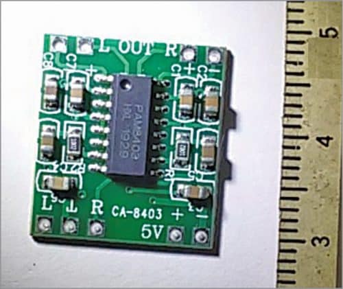
In order to get a good sound and also minimise on parts size, we recommend the PAM8403 mini audio board (Fig. 7). No external components are needed, just connect pin 3 of Arduino to PAM8403 board and provide 5V supply to the board. Connect the speaker to anyone of the two points marked R (right) and L (left) in the PAM8403 board depending on to which pin the connection from digital pin 3 of Arduino board is given to the input side – R or L. The PAM8403 board is the size of a one-rupee coin and is thin, because all parts on this board use SMD components. (During testing at EFY Lab, the LM358 based amplifier was first tried but it gave quite a low sound.)
Download Source Code
Alternative possibilities
Instead of the LED Alarm clock, one can change the program to make it a seconds timer that could be used as a 100-metre race timer, for instance. For this, pin 9 used for the buzzer can instead be used as input for the limit switch to stop it when the racer reaches the goal line. This pin should be set up by the code line ‘input pull up.’
It is possible to show temperature also on the display in degrees Celsius. The analogue input pin A0 of Arduino can be wired to an LM35 temperature sensor. The ‘analog reference’ may be set up at internal 1.1V full-scale for maximum accuracy. The clock and temperature can be shown together. The program can be written to show the temperature for just five seconds at the beginning of every minute and then revert back to clock.
Prof. K. Padmanabhan retired as a professor at A.C. Tech and the University of Madras
Talking clock. In the text it is mentioned that DS3231 or DS1307 can be used without change to sketch code. I see in the video that the DS3231 is used, but in the sketch “RTC_DS1307 rtc” is used. I placed DS3231 in the sketch, but get an error. It says, “class RTC_DS3231 has no member named ‘ísrunning’ Please advise what I do, I am using DS3231, (more accurate) will it compile leaving RTC_DS1307 rtc in the sketch.
Many thanks