


 Soldering irons are available in different wattage and usually run at 230V AC mains. However, these have no temperature control. Low-voltage soldering irons (e.g., 12V) generally form part of a soldering station and are designed to be used with a temperature controller. A proper temperature controlled soldering iron or station is expensive. Here is a simple circuit that provides manual control of the temperature of an ordinary 12V AC soldering iron.
Temperature Controlled Soldering Iron Circuit
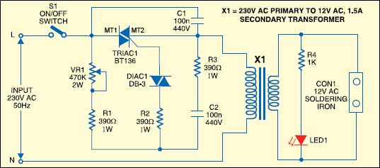
The circuit consists of power switch S1, TRIAC1, DIAC1, potentiometer VR1, resistors R1 to R3, capacitors C1 and C2, and step-down transformer X1. Adjusting the resistance of VR1 changes the charging rate of C1 to regulate the conduction angle of TRIAC1, and hence the output power (heat) of the low-voltage soldering iron connected to X1. The red LED (LED1) indicates the power status.
Assemble the circuit on a general-purpose PCB and enclose in a suitable plastic box. Since the front end of the circuit is directly connected to 230V AC mains supply, never attempt to operate the circuit without the cabinet. Use a heavy-duty potentiometer with plastic shaft and a knob for temperature control.

The article was first published in January 1997 and recently been updated.


Hello. Why I control 220v section of circuit instead 12v section? And what hapend with the LED in case of reducing tension?
Can we use a 24 volts soldering iron instead of 12 volt by just changing the transformer and with no other changes in the circuit? Because as far as I know 24 volts soldering iron are more easily available in the market.