We’re excited to share that we build a smart touch sensor switch module, made to bring modern features to your products or devices without the hefty price tag.
This project is covered by the following Open Source license: Creative Commons Non-Commercial Similar Adaptations. For commercialisation of our designs, please email to [email protected]. For full details of this license, please refer to license details published at the end of this project.
Why We Made It?
Touch switch modules are gaining popularity because they use a touch sensor switch, eliminating the need for mechanical components.

Plus, they can work behind materials, providing a sleek and modern finish to product designs.
The Cost Dilemma in Touch Switch Systems:
Designing systems with touch switches often increases the overall Bill of Materials (BOM) cost. To keep products affordable, design engineers sometimes resort to using tactile switches, which are priced at 10 to 15 rupees in SMD.
However, this compromises the product’s aesthetics, making it look outdated. The engineers may even need to add a hole or cut a mark on the product to access the tactile push switch.
Our Solution – A Cost-Effective Touch Sensor:
Today, we present a touch sensor that costs around 10 rupees and works from behind materials. You can discreetly place the sensor behind any conductive material on the body.
When you touch it, the sensor senses it. The beauty of this design is its programmability in 4 different ways.
How It Works?
The circuit provided can be integrated into your product design. Alternatively, you can download the design and use it as a standalone sensor module. Enhance your product’s user experience without breaking the bank!
Ready to add a touch of innovation to your product? Let’s learn step-by-step, how you can make your own touch sensor at just Rs. 10!
The material used in the project is listed in the table below.
Bill of Material

Touch Sensor Switch – Circuit Design
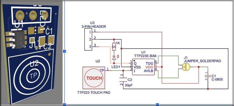
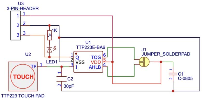
The circuit diagram of the DIY Touch Sensor Switch is easy to build.
You can connect the components according to the circuit diagram, we have provided in the figure below and your touch sensor is ready.
You can either integrate our circuit into your device design by downloading the Gerber file or design your own sensor module and use it for different purposes.
Touch Sensor IC
According to the datasheet, the Touch sensor IC TTP223 has the following pinout.
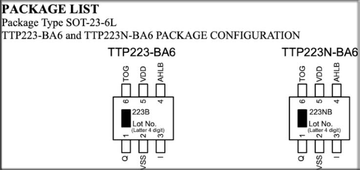
According to the datasheet of the IC, the operating voltage for the TTP223-BA6 typically ranges from 2.0V to 5.5V and requires a sensing electrode for touch detection.
This can be a piece of conductive material (e.g. a piece of copper or a conductive pad) connected to the appropriate pin on the IC. The TTP223-BA6 provides an output signal that changes when a touch is detected.
You’ll need to connect this output to your microcontroller or the load you want to control based on touch.
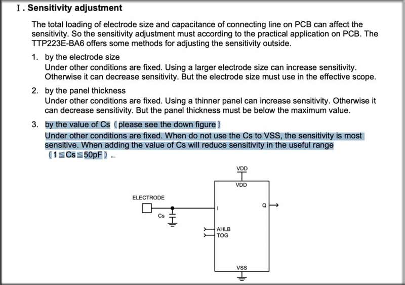
According to the IC datasheet, the IC sensitivity effect with electrode size and connecting lines on PCB. The sensitivity of these can be calibrated and adjusted as per requirement using the capacitor at the electrode pin “I” and GND.
The value of the capacitor for adjustment can be range from 1pF to 50 pF. you can refer to the datasheet for more details.
IC Working Modes
The IC working can be programmed in 4 different ways by adding a solder jumper to TOG pin 6 and Pin 4.
It provides four different options for the behavior of the Q (CMOS output) pin based on the TOG and AHLB settings.
1. Push Mode:
- TOG = 0 (Direct output)AHLB = 0 (CMOS active high)
2. Toggle Mode:
- TOG = 1 (Toggle output)AHLB = 0 (CMOS active high)
It can be used for applications where you want to toggle a state or switch something with each touch, such as a light switch.
3. Toggle Mode with Power-On State = 0:
- TOG = 1 (Toggle output)AHLB = 1 (CMOS active low)
This can be used for applications where you want a particular default state when the IC powers on, and then toggle the state with each touch.
4. Toggle Mode with Power-On State = 1:
- TOG = 1 (Toggle output)AHLB = 1 (CMOS active low)
This mode is also useful when you want a specific default state when the IC powers on and then toggle the state with each touch.
So you can use the solder jumper of the solder jumper pad in between those pins to change the mode.
You can connect the components according to the circuit diagram, we have provided in the figure below and your touch sensor is ready.
You can either integrate my circuit into your device design by downloading the Gerber file or design your own sensor module and use it for different purposes.

You can also check our other Touch Switch Projects that we build previously like Simple Touch Sensitive Switch, Touch Switchboard Circuit.
Testing and Gerber File
After connecting the components based on the circuit diagram, proceed to connect the solder jumper according to the desired pin function.
Now, link the LED to the output pin, and upon touching the electrode, the LED will illuminate. Find the Gerber file for the PCB attached below.