


A regulated DC power supply is one of the most useful tools for electronics hobbyists, students, and repair technicians. During circuit development and testing, different electronic circuits require different DC voltage levels. Instead of relying on multiple batteries or fixed-voltage adaptors, a universal bench power supply provides adjustable, stable DC output for a wide range of applications.
The circuit presented here is a simple linear regulated power supply that provides dual fixed outputs of +12V and –12V, along with an adjustable DC output from approximately 1.2V to 22V. The design is based on the widely used LM7812, LM7912, and LM338 voltage regulator ICs.
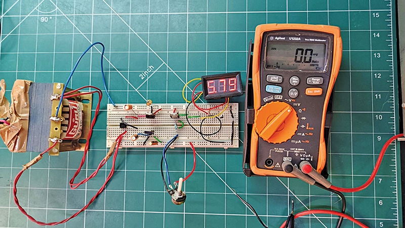
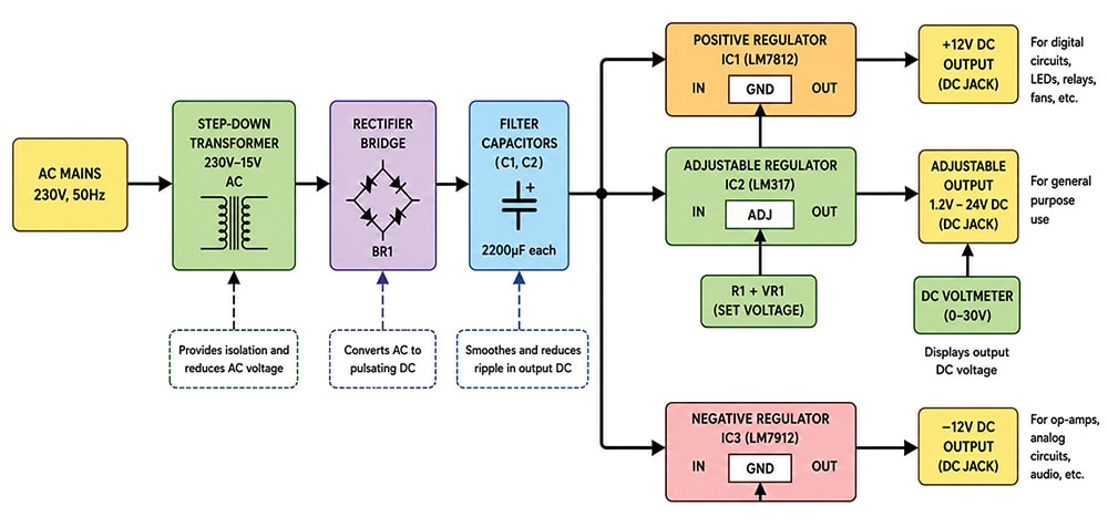
The power supply uses a step-down transformer, a bridge rectifier, filter capacitors, and linear voltage regulators to produce smooth, reliable DC voltages. The LM338-based adjustable section delivers higher current than conventional adjustable regulators, making it suitable for powering small electronic systems, op-amp circuits, sensor modules, and embedded systems. Fig. 1 shows the author’s prototype, while Fig. 2 shows the block diagram of the universal power supply.
Block diagram
The block diagram of the universal power supply shows how 230V AC mains voltage is converted into regulated DC outputs. A step-down transformer reduces the mains voltage to a safer low-voltage AC level and provides isolation. The bridge rectifier (BR1) converts the AC into pulsating DC, while capacitors C1 and C2 filter the voltage and reduce ripple.
The filtered DC is supplied to three regulator sections. IC LM7812 provides a fixed +12V output, LM7912 generates a fixed –12V output, and LM338 provides an adjustable output from about 1.2V to 22V DC using a potentiometer. A DC voltmeter is used to monitor the adjustable output voltage.
Circuit and working
Fig. 3 shows the circuit diagram of the universal power supply. It is built around a step-down transformer (X1), a bridge rectifier (BR1), the positive fixed-voltage regulator LM7812 (IC1), the negative fixed-voltage regulator LM7912 (IC2), the adjustable variable-voltage regulator LM338 (IC3), and a few other components. It provides dual regulated outputs of +12V and –12V along with an adjustable DC output ranging from approximately 1.2V to 22V, making the circuit suitable for laboratory applications and electronic system development.