


 Presented here is a simple, low-cost USB interface signal monitoring circuit. It can be used to monitor signal activity for most of the USB interfaces.
The circuit finds following applications:
1. It can be connected to a cable with USB interface to check data signals in the wires
2. It can be connected between two USB cables, with the first cable connected to a computer and the second to a peripheral device with a USB interface, to monitor various signals
3. It can be connected to a USB power supply or USB battery charger and other devices with USB interfaces to check power signals
4. It can also be connected to a voltmeter or an oscilloscope to check voltage signals
In all these cases, the maximal USB cable length should be limited as specified under the USB standard.

USB interface signal monitoring circuit
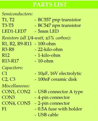
Circuit diagram of the USB interface signal monitor is shown in Fig. 1. It is built around two BC557 pnp transistors (T1 and T2), three BC547 npn transistors (T3 through T5), seven LEDs (LED1 through LED7), two USB connectors (CON1 and CON2), and a few resistors and capacitors.
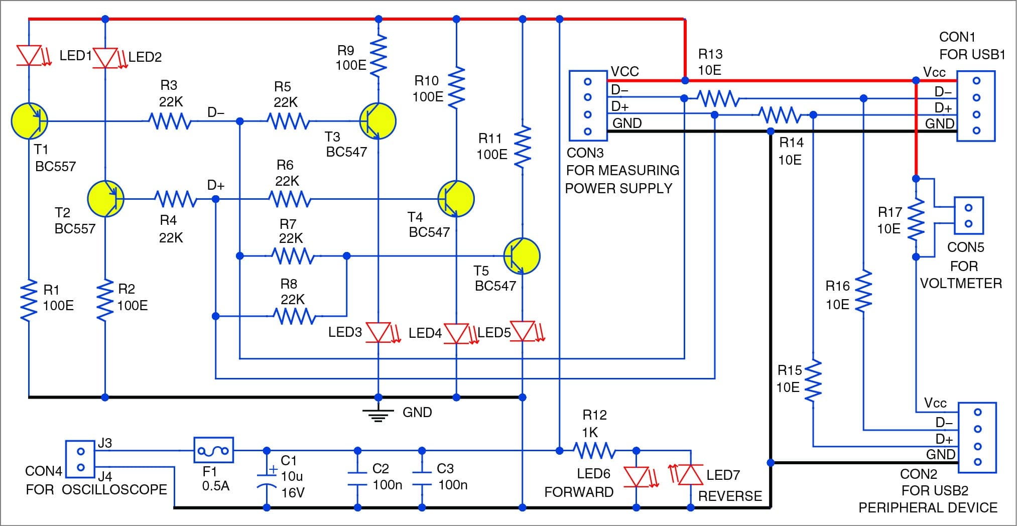
Fig. 1: Circuit diagram of the simple USB interface signal monitor
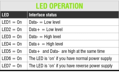
Connect one of the two USB connectors to a computer, and the other to a peripheral with USB interface. LED6 and LED7 show the data bus status. You can also use voltmeters, oscilloscopes and other test equipment to monitor the USB interface activity.
LED Operation table details the LEDs’ indication in the circuit. Voltage drop across all the LEDs should be around 1.6V, and the LEDs should be able to produce light at current levels as low as 1mA. Resistors R1, R2 and R9 through R11 are used to limit the current flowing through the LEDs. You can increase the resistor values from 100 ohms to 500 ohms as per your requirements.
Resistors R3 through R8 are used to limit the base current of transistors T1 through T5 and the load of DATA+ and DATA-.
These resistors should have the maximal possible values in order to reduce the USB load. The exact values of these resistors depends on the DC gain of the transistors and the current required for the LEDs.
Power supply
The circuit operates in the full power supply range of the USB interface. If polarity of the supply from the USB connector is reversed, LED7 glows. Otherwise, it remains off and LED6 glows during normal (forward) operation.
Current measurement
Resistor R17 and connector CON5 are used to measure the current of the interface. For example, if the power supply current is 0.3A, the voltage drop across resistor R17 will be 30mV. Use a digital voltmeter or oscilloscope to measure the voltage drop across R17.
Oscilloscope
You can connect the oscilloscope to 4-pin header CON3 or to 2-pin header CON5. Also, you can use connector CON4 to connect an oscilloscope, voltmeter or module operating from +5V supply.
Adjustment
The circuit does not need any special adjustment to operate. However, in some cases, you may need to change the values of some resistors, and use transistors with high DC gain and LEDs with low forward voltage drop, but that’s very rare.
Construction and testing
A PCB layout of the USB interface signal monitoring circuit is shown in Fig. 2 and its components layout in Fig. 3. After assembling the circuit on the PCB, enclose it in a suitable box such that all the connectors are easily accessible. Mount the LEDs (LED1 through LED7) on the front side of the box for visual indication of signals.
Download PCB and component layout PDFs: click here
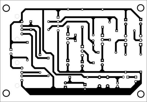
Fig. 2: PCB layout of the USB interface signal monitoring circuit
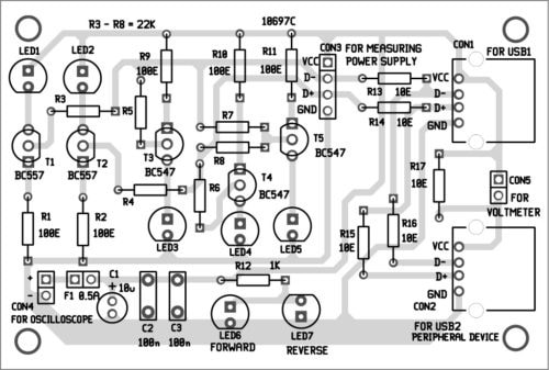
Fig. 3: Components layout for the PCB


Does it work between a PC and USB pen drive?
Hi, just wanted to know if this pcb could be used between a PC and an USB pen drive. I want to signalize traffic between my PC and my flash drive. Thanks!