Due to coronavirus we are now used to alcohol based sanitisation liquids and sprays but what about disinfecting items like goggles, keys, mobile phone, watch, currency notes, laptop, courier packets, etc that we handle? A convenient solution for disinfecting such items is an ultraviolet (UV) sterilisation box that you can build yourself.
Ultraviolet is electromagnetic radiation with wavelength of 10 to 400nm. It has shorter wavelength than visible light but longer than x-rays. The wide range of UV radiation is grouped into three main categories:
- UV-A with wavelength of 315 to 400nm
- UV-B with wavelength of 280 to 315nm
- UV-C with wavelength of 100 to 280nm
Across the world, UV-C sterilisation is an established method for inactivating pathogens, viruses, and bacteria. UV-C disrupts the DNA of pathogens and impairs their ability to perform vital cellular functions. The effectiveness of this germicidal exposure depends on the duration of exposure and the intensity and wavelength of the UV radiation. It is therefore necessary that sufficient UV-C light reaches all parts of the object being disinfected.
Features of this steriliser are:
- UV-C lamps operating at 254nm wavelength for effective germicidal effect
- Enclosed UV leak-proof box
- Reflective sides for maximising reflections and giving effective 360-degree coverage
- Magnetic hold of door/lid to keep it securely closed
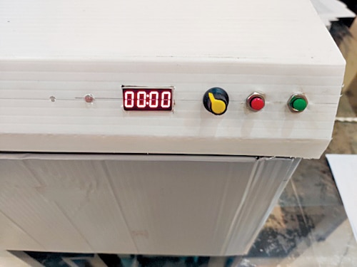
- Rotary switch for setting exposure time from 1 to 10 minutes
- Timer can be paused, if desired
- Simple operation using Start/Resume and Stop/Pause buttons
- Display showing remaining time and alert messages
- Safety feature that shuts off the UV lamp if the door/lid of the box is opened
Construction
The UV steriliser can be made using a suitable-size stiff cardboard or wooden box, or any other sturdy box. (Direct exposure to UV-C rays is harmful to humans, so build a proper enclosure.) The author’s prototype was built using an empty printer box as shown in Fig. 1.

The top of the box was sealed and fixed while a slot was cut on the front side of the box as shown in Fig. 2. A 3cm edge (frame) was left on all sides of the opening so that the door could rest (close) along these edges. The door can be built using a cardboard sheet that is at least 2cm bigger than the opening to block the UV light properly.

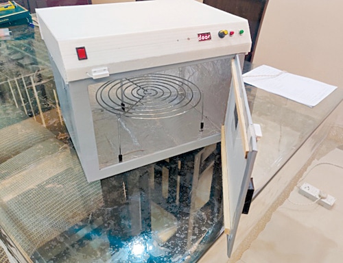
A hinge can be made on one edge by cutting a 3cm strip from the door and sticking it again with a sturdy tape or a cloth strip. On the opposite edge three neodymium magnets can be embedded inside the cardboard to serve as a secure lock for the door. A thin iron strip (such as a piece of an old hacksaw) may be attached to the side edge of the box to which the magnets can stick.
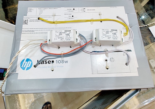
Stick kitchen aluminium foil or silver craft paper on all inner sides of the box so that the UV light scatters all over inside the box. The outer side of the box can also be covered with craft paper. Install the two 11W UV tubes on ceiling of the box using ties. Draw the end wires connected to the tubes outside the top of the box where the two chokes are installed as shown in Fig. 3.

Circuit and working
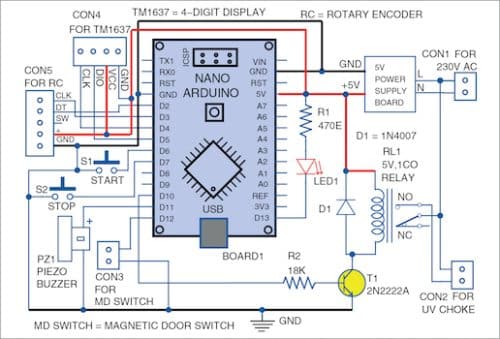
The controller is built around an Arduino. Arduino Pro can be used, which has a small footprint, though any Arduino variant would work. Circuit diagram of the UV sterilisation box is shown in Fig. 4. It comprises a TM1637 module, 5V DC power supply module (Module1), Arduino Nano (Board1), 5V single-changeover relay (RL1), a rotary switch, a magnetic door switch, two 230V AC operated UV tubes, two chokes, and a few other components.

The software sketch can be downloaded from EFY website and uploaded to the Arduino using the Arduino IDE.
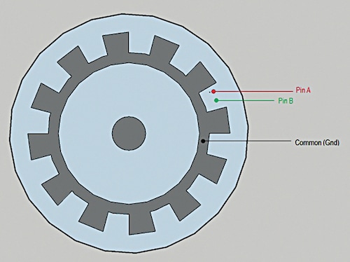
A rotary encoder is used for setting time-period. Though it looks like an analogue potentiometer, it is a digital device that can be fully rotated without any end stops. It does not give any absolute value but can be interpreted to give the direction of motion, and the pulses generated can be counted to give the new value. The most common rotary encoder is the scroll wheel on a computer mouse. Just like a mouse, the rotary encoder can be rotated and clicked (pressed). In this circuit, the inbuilt press switch is not used. Inside the encoder there is a slotted disk connected to the common ground pin C, and two contact pins A and B as shown in Fig. 5.

[signinlocker id=”87626″]
In addition to these three pins, there are two pins for the momentary switch (not used). When the switch is rotated clockwise, pin A gets grounded before pin B, and as the knob is rotated further pin A goes low before pin B. After each full cycle of the pulse, a click can be felt as there are detents (stops). There are 20 such detents in one full rotation.
Similarly, when the knob is rotated counter-clockwise, the pulse sequence changes as pin B goes high first followed by pin A. The pulse train sequence is shown in Fig. 6.

The encoder used here has five pins as shown in Fig. 7. Pin DT of encoder is connected to pin 2 of Arduino while CLK pin is connected to pin D3 of Arduino. The + and GND pins of encoder are connected to 5V and GND pins of Arduino, respectively.

Software
The software program UVTimer.ino can decode the direction of rotation of encoder just by checking the level of pin B when pin A changes from high to low. Pin B would be 1 if it goes clockwise and 0 if it goes counter-clockwise. A variable is saved, which keeps track of the number of pulses and reflects the new value after rotation. The initial value has to be given (0 in our case). Since the encoders are mechanical, there is a lot of bounce when position changes, requiring debouncing in software.
All the above tasks are handled by NewEncoder library. Pins A and B of the encoder need to be necessarily connected to the interrupt pins of the Arduino as the library uses interrupts to track the rotation. An Arduino Uno, Nano, or Pro version has only two hardware interrupt pins, viz, pins 2 and 3. The encoder will not work if connected to any other digital input pin.
This library should be downloaded from https://github.com/gfvalvo/NewEncoder. After unzipping the downloaded file, the NewEncoder-master folder should be copied to the …\Documents\Arduino\Libraries folder.
A 4-digit, 7-segment display is used for displaying the time. A display module based on TM1637 IC has been used as it requires only two pins on an Arduino for displaying the digits. The clock pin of the module is connected to pin 4 while the data pin is connected to pin 5 of the Arduino.
The module uses TM1637 library by Avishay Orpaz. This library can be installed using the ‘Manage Libraries’ option under the ‘Sketch/Include Library’ menu of Arduino IDE.
Two momentary press switches (S1 and S2) are used as Start and Stop buttons. One pin of the Start button is connected to pin 6 while the second is grounded. Similarly, the Stop button is connected to pin 7 of the Arduino.

There is no need to use pull-up resistors as the internal pull-ups are activated in software. The button press is handled using OneButton library by Matthias Hertel. It can also be installed using ‘Manage Libraries’ option under ‘Sketch/Include Library’ menu of the IDE.
A magnetic door sensor switch is fixed on the upper edge of the door as shown in Fig. 8.
The magnet section is connected to the door whereas the reed switch part is connected to the box. One wire of the reed switch is connected to pin D12 of Arduino while the second wire is grounded. The mode of D12 pin is set as INPUT_PULLUP so that the internal pull-up resistor of pin D12 is activated.
A 5V buzzer is connected to pin D11 of Arduino to give warning signals.
A cardboard’s lid for the box serves as a cover for the chokes and the front edge serves as the control panel. The circuit is placed inside this lid as shown in Fig. 9.

A 5V relay is connected to pin D10 of Arduino via a 2N2222 NPN transistor whose base is connected to 18k resistor to limit the base current. The relay will be activated as long as pin D12 is held high. A readymade relay module can also be used instead of the relay and transistor. However, since relay modules are activated using a low level, suitable changes need to be made in software.
The NO terminal of the relay is connected to the UV chokes so that the UV lights are switched on when the relay is activated. An indicator LED connected to pin D13 of Arduino lights up when the UV light is on.

Using the UV steriliser
The disinfection process is dependent on the duration and strength of the UV exposure. Small items like masks and keys should be exposed for a minimum of two to three minutes while for larger items the exposure should be proportionately increased. Use a small steel rack to raise the items inside the box so that UV light can reach the lower parts of the items also. The author used a spare cake rack that came as accessory to a microwave oven.
First keep the items to be disinfected on the steel rack and close the door. The display will indicate ‘Door’ while the door is open. The display will change to ‘00:00’ when the door is closed. Now you can set the time using the rotary switch. Any time from 1:00 minute to 10:00 minutes can be set. If you rotate the dial of encoder further, a beep will sound as the min and max values have been set in the software.
Now press the Start switch. The relay will switch on and the timer will start the countdown. The time remaining will appear on the display. The countdown will continue for the set time and on completion, ‘End’ would be displayed and a long beep sound heard. Now you may open the door and take out the items.
On closing the door, the time period will be set automatically to the last setting. If desired, it can be changed using the rotary switch, or more items may be disinfected with the old time setting. Shadows can restrict disinfection, so do not keep too many items in one go to avoid shadows.
If Stop button is pressed while the countdown is going on, the display will show ‘Stop.’ On pressing ‘Start’ button the countdown will resume and complete as usual. However, if door is opened during sterlisation, the process will be cancelled and on closing the door, the last set time will be restored. The UV lights shut off and sanitisation process stops as soon as the door is opened. While setting the time, it can be reset to ‘00:00’ by pressing the ‘Stop’ button.
A PCB layout for this UV steriliser box is shown in Fig. 11 and its component layout in Fig. 12. Before assembling the circuit do not forget to upload UVTimer.ino into Arduno Nano. Assemble the circuit on PCB and enclose the PCB along with Arduino and other parts in suitable UV steriliser box as explained above.


Download PCB and component layout PDFs: click here
Download Source Code
The author has been using the sanitiser to sterilise face masks after every use. Milk and other packets are also sanitised by him before use. So go ahead and sanitise your items using this simple sanitiser.
Caution. Exposure to UV-C rays is harmful to humans. Do not try to test or expose yourself to UV lights directly.
Ashok Baijal is a regular contributor to EFY. He currently retired and is now working on home automation projects
[/signinlocker]
do you have the circuit diagram for this project? if have pls tell me i need it for my Final year project references
Hi Ammar, the circuit diagram is present within the article.
other question, where do u find the chokes needed for this UV box I couldn’t find it online and also is there a video of the UV box being build pls if u have
The author Ashok Baijal replies:
I purchased the items online from Amazon but should be available in the electrical markets. They are commonly used in water filters. I used the Osram brand.
2. I did not make a video while constructing the device but photos are given in the article. It is a simple build. The chokes and tubes are held to the carton box using zip ties.
3. I have been using my device for sanitizing the mask and keys, phone after every use without a problem even today.
Total cost of the project?
Dear Anwesha,
Calculate the cost at yourself as it varies from place to place.
Regards