


 Presented here is a window alarm annunciator based on Arduino Uno board. An annunciator is mainly used in process plants, power plants and industries to monitor various plant conditions to alert operators about abnormal conditions or parameter deviations.
It can also be used as a security/fire alarm.
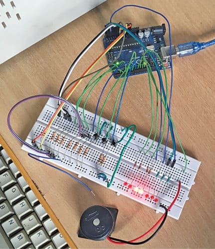
The author’s prototype of window alarm annunciator based on Arduino is shown in Fig. 1.

Circuit and Working
The circuit diagram of the window alarm annunciator is shown in Fig. 2. It is built around Arduino Uno board (board1), seven LEDs (LED1 through LED7), three tactile switches (S1 through S3) and a few discrete components.
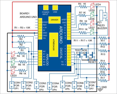
This annunciator has seven inputs connected across connectors CON1 through CON7 for initiating the alarm through normally-open (NO) contacts.
There are also three input switches (S1 through S3) for test, acknowledge and reset. There are eight outputs, out of which seven are connected with LEDs, corresponding to seven input alarm contacts, while the eighth output is provided for the buzzer.
(The buzzer can be replaced with a hooter using additional circuitry)
All alarm inputs are designed for NO contacts. Apart from digital pin 2 through pin 13 of Arduino, analogue pin A0 through pin A5 are also used as digital I/O pins to monitor the seven different input conditions.
If any input alarm contact is closed, the corresponding output LED will blink/flash at a fast rate and the piezo buzzer will be activated to attract the attention of the user, or people, nearby. The alarm can be stopped by pressing the acknowledge pushbutton switch (S2).
This will de-active the piezo buzzer and the LED will blink at a slower rate. That is, if alarm input contact is opened, alarm sound will stop but the LED will continue to flash at a slow rate. When reset button (S3) is pressed, the LED will go off completely.
Let us take an example. Initially, all inputs are open, so all LEDs are off. If there is problem with the first machine, first input I/P1 at CON1 will close, LED1 will flash at a fast rate and PZ1 will make an alarm sound.
When S2 is pressed, with I/P1 closed, PZ1 will be off but LED1 will stay on. When S2 is pressed, with I/P1 open, PZ1 will be off and LED1 will flash slowly until S3 is pressed momentarily.
Test pushbutton switch S1 is provided to test the LEDs and the buzzer. When S1 is pressed, all window alarm LEDs will glow steadily, and the buzzer will be activated. This will continue till S1 is released.
Arduino Code for Window Alarm Annunciator
The software is written in Arduino programming language using Arduino IDE version 1.8.5. Before uploading the given sketch/program to Arduino Uno, ensure that elapsed Millis library function is available in Arduino IDE (Sketch>Include libraries>Arduino libraries).
If not, download elapsedMillis-master folder from source.efymag.com. Then, include the zip file by following the steps given below.
Sketch>Include libraries>Add. ZIP Library…>and browse the location where elapsed Millis file is saved. After adding the above library function, ensure that it appears in the list of library functions. Now, upload Annunciator.ino sketch file to the board.
Download Source Folder
PCB Design
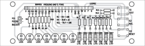
A PCB layout of the window alarm annunciator is shown in Fig. 3 and its components layout in Fig. 4. After assembling the circuit, enclose it in a suitable box, along with Arduino Uno. Fix all LEDs on one side of the cabinet and piezo buzzer on the other. Power supply for the circuit is used through Arduino board and connected through the USB port of the laptop/desktop.

Download PCB and Component Layout PDFs: click here
Construction and Testing
All inputs, I/P1 through I/P7, are potential-free external NO contacts with a common ground rail. That is, all inputs coming from the appliances/machineries should be NO. Input contacts should close when problems like overload or short-circuit occur in the load of one or more appliances/machineries.
For easy and quick testing, assemble the circuit on a breadboard, as per the given connection diagram. All inputs can be initiated, including acknowledge, test and reset inputs, by pressing the respective switches.
Caution!
Only potential-free external NO contacts should be used as alarm contacts (CON1 through CON7) with a common ground. Otherwise, external voltage injected into the circuit will damage Arduino Uno.
If long cables are used for alarm input, EMI suppression circuits/optocoupler circuits should be added to prevent spurious operation or damage.
Enhancements for a Reliable and Versatile Window Alarm Annunciator
- Customizable Outputs: You can use the output pins to operate other alert mechanisms, such as relays or a siren, to generate louder alarms.
- Remote Monitoring: Use an IoT module (such as the ESP8266) to send notifications to a smartphone or remote system when the alarm is triggered.
- Power Backup: Include a battery backup to provide continuous operation during power outages, increasing reliability for home or industrial security.
- User-Friendly Enclosure: Create an enclosure that clearly labels the LEDs and buttons, making the system simple to understand and use for anyone.
- Expandable Inputs: If you’re monitoring numerous points, utilize a multiplexer to enhance the number of inputs, allowing the system to accommodate more sensors or connections.
Also Check: Collection of our tested Arduino projects
P. Balasubramanian is a retired scientific officer from Nuclear Power Corp. of India Ltd (NPCIL). His areas of interest include microcontrollers and power electronics
This article was first published on 9 November 2019 and recently updated in 2024.
Hi sir,
How can I find source file of this project.
Please help me.
Thanks and regards
Anu.CJ
The Source Folder is present within the article for download, please check.
sir pls share the source file here, i unable to download the source file
please share
by mail: [email protected]
mobile: 7502355410
Hi, we have updated the article, you can download the file now.