


 Keep away intruders with this compact electrified window charger. The charger produces non-lethal shocks that are strong enough to threaten intruders.
Window Charger Circuit
The circuit given below uses IC CD4047 as a free-running astable multivibrator. Capacitor C1 and preset VR1 are timing components. The pulse repetition rate is determined by the value of 4.4C1×VR1. The frequency can be varied with the help of preset VR1.
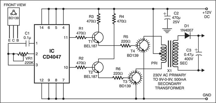
The IC generates complementary square wave signals at pins 10 and 11. Transistors T1 and T2 serve as drivers for the following push-pull amplifier stage. A high-voltage generator, realised using step-up transformer X1 and medium-power transistors T3 and T4, follows the astable multivibrator. The step-down transformer is used for reverse function (step-up) and its output is rectified by diode D1, filtered by capacitor C3 and then given to window (made of metal frame).

Read other exciting circuit articles
The project was first published in Jan 2004 and has recently been updated.
Sir, Instead of BEL187+BD139, can I use BD677 NPN Power Darlington Transistor TO-126 Package?
Dear Sir,
Although we have not tested the project with BD677.
Meanwhile we think that you can use (replace) BD677 NPN Power Darlington Transistor
in place of BEL187+BD139.
Regards