


 This project presents the implementation of a MATLAB graphical user interface (GUI)-based approach to wirelessly control the movement of a robotic car. Commands to move the car in forward, reverse, right and left directions are sent from the GUI, and processed by Arduino present on transmitter side. After processing the command(s), a code is sent wirelessly to the receiver.
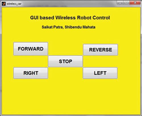
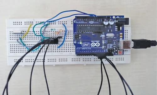
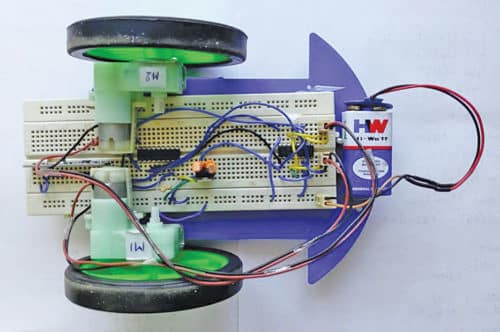
The receiver side decodes the code and makes the robot move accordingly. MATLAB-based GUI for wireless control of the robot is shown in Fig. 1. Prototypes for the transmitter and the robotic car (present on receiver side) are shown in Figs 2 and 3, respectively.
Circuit and working
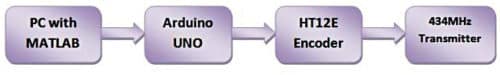
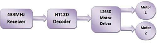
Block diagrams of transmitter and receiver sides are shown in Figs 4 and 5, respectively.
Components used in this project are as follows:

Arduino Uno board
Arduino Uno is an AVR ATmega328P microcontroller (MCU)-based development board with six analogue input pins and 14 digital I/O pins. The MCU has 32kB ISP flash memory, 2kB RAM and 1kB EEPROM. The board provides the capability of serial communication via UART, SPI and I2C. The MCU can operate at a clock frequency of 16MHz. In this project, digital I/O pins 9, 10, 11 and 12 of Arduino are configured as output pins.
HT12E
The 212 series encoders are generally used for remote control system applications. These encoders are capable of encoding information that consists of n address bits and 12-n data bits. Each address/data input can be set to one of the two logic states. Programmed address/data are transmitted together with header bits via an RF or IR transmission medium upon receipt of a trigger signal.
HT12D
The 212 decoders are a series of CMOS LSIs for remote control system applications. These are paired with HT12E encoders. Decoders receive serial addresses and data from programmed 212 series of encoders that are transmitted by a carrier using an RF or IR transmission medium.
The decoders compare serial input data three times continuously with their local addresses. If no error or matched codes are found, input data codes are decoded and then transferred to output pins. The 212 decoders are capable of decoding information that consists of n bits of addresses and 12-n bits of data. For a valid transmission, address bits of both encoder and decoder must be the same.
434MHz TX-RX modules
These 434MHz transmitter (TX) and receiver (RX) modules are electronic devices used for transmitting and receiving RF signals between two devices. These are used widely in electronic design, owing to the difficulty of designing radio circuitry. Carrier frequency of the module used here is 434MHz.
L293D
This is a dual H-Bridge high-current motor driver IC. It is used here since digital pins of Arduino cannot source enough current to drive the motors of the robotic car. H-bridges are also useful in controlling the direction of rotation of the motors.
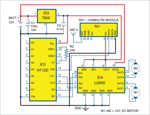
Enable pins (pins 1 and 9) of the IC being active high are connected to 5V. Input pins IN1 through IN4 of L293D are connected to output pins D11 through D8 of HT12D, respectively. Output pins OUT1 through OUT4 of L293D IC are connected to motors M1 and M2, as shown in the circuit diagram of receiver side.
7805
This is a three-terminal, 5V fixed-voltage regulator with output current up to 1A. Although designed primarily as a fixed-voltage regulator, it can be used with external components for adjustable voltage and current.
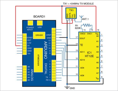
Circuit diagrams of transmitter and receiver sides are shown in Figs 6 and 7, respectively.
Software
Arduino IDE 1.6.5 is used for programming Arduino Uno. The GUI application program was developed in R2014a version of MATLAB. The procedure for installing Legacy MATLAB and Simulink Support for Arduino package was described in ‘Logging Sensor Data In MS EXCEL Through MATLAB GUI’ article published in June 2018 issue.
After setting up the path for the package, open the source code file for this project, titled wireless_car.m, from MATLAB. Edit the COM port (in the line, a=arduino(‘COM8’)) with the port number in your PC where Arduino Uno board is installed.
After running the file, MATLAB will try to communicate with the board. After successful communication is established, you can wirelessly control the robot by pressing the appropriate pushbutton in the GUI.
A particular pushbutton of the GUI, when pressed, executes callback function corresponding to it in this MATLAB program, wireless_car.m. Within that function, instructions to set/reset digital I/O pins 9, 10, 11 and 12 of Arduino are executed.
Four digital I/O pins of Arduino are connected to data pins AD8 through AD11, respectively, of HT12E encoder. After a pin is set or reset, the encoder scans the status of the digital pins and transmits the digital pins’ status wirelessly to receiver side using 434MHz wireless transmitter (TX1).
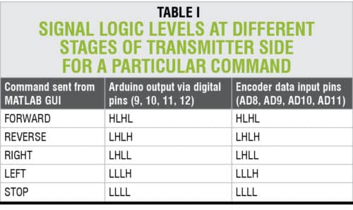
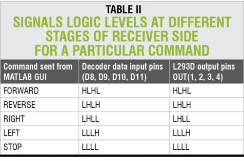
Receiver side receives the data, and HT12D decoder present on receiver side decodes it and sets its output pins D8, D9, D10 and D11, accordingly. These output pins of the decoder are, in turn, used to control output pins of L293D motor driver. Signal logic levels at different stages of the circuits for proper controlling of the robotic car are listed in Tables I and II.
Download Source Folder
Construction and testing
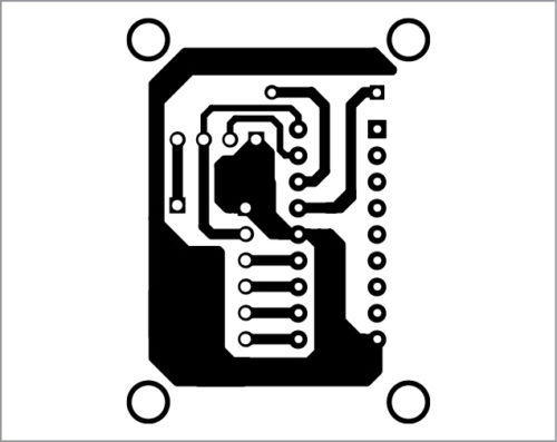
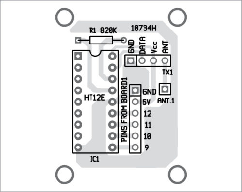
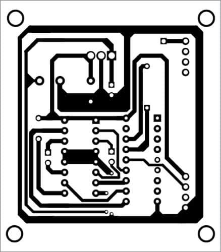
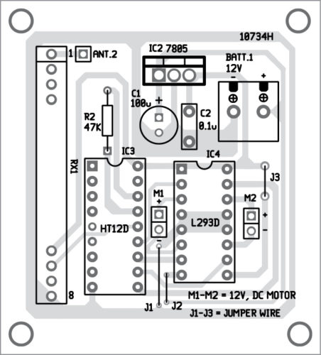
APCB layout for transmitter side is shown in Fig. 8 and its components layout in Fig. 9. An actual-size PCB layout of receiver side is shown in Fig. 10 and its components layout in Fig. 11.
Download PCB and Component Layout PDFs: click here
After mounting the components on the transmitter PCB, connect the respective Arduino pins to the marked pins, as shown in Fig. 9.

Similarly, assemble the components on the receiver PCB. Mount the receiver PCB on the robot chassis. A 9V battery, as shown in the prototype, may not be powerful enough to drive the motors. It is recommended to use a 12V battery instead. Use suitable DC geared motors and wheels.
Saikat Patra is passionate about electronics and MCU-based embedded system applications
Shibendu Mahata is M.Tech (gold medallist) in instrumentation and electronics engineering from Jadavpur University. Currently, he is pursuing PhD from NIT Durgapur. He is interested in designing MCU-based real-time embedded signal processing and process control systems
Hey there
Im having a problem with this project and i hope you can help me
After i made the circuits and burned the code the car only applied the first command
For example if i send ‘forward’ after i plug in the battery it starts moving but if i send ‘stop’ it keeps going forward until i unplug and then replug the battery
I tried everything and changed all the ic’s except the l293d because it was hard to find but with noluck
I hope someone can help me understand the problem in order for me to find a proper solution
Thank you in advance