


 Normally, home appliances are controlled by means of switches, sensors, etc. However, physical contact with switches may be dangerous if there is any shorting. The wireless switch circuit described here requires no physical contact for operating the appliance. You just need to move your hand between the infrared LED (IR LED1) and the photo-transistor (T1). The infrared rays transmitted by IR LED1 is detected by the photo-transistor to activate the hidden lock, flush system, hand dryer or else.
Wireless switch circuit
This circuit is very stable and sensitive compared to other AC appliance control circuits. It is simple, compact and cheap. Current consumption is low in milliamperes.
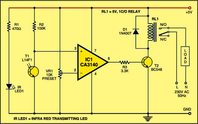
The circuit is built around an IC CA3140, IRLED1, photo-transistor and other discrete components. When regulated 5V is connected to the circuit, IR LED1 emits infrared rays, which are received by photo-transistor T1 if it is properly aligned. The collector of T1 is connected to non-inverting pin 3 of IC1. Inverting pin 2 of IC1 is connected to voltage-divider preset VR1. Using preset VR1 you can vary the reference voltage at pin 2, which also affects sensitivity of the photo-transistor.

Op-amp IC1 amplifies the signal received from the photo-transistor. Resistor R3 controls the base current of transistor BC548 (T2). The high output of IC1 at pin 6 drives transistor T2 to energise relay RL1 and switch on the appliance, say, hand dryer, through the relay contacts.The working of the circuit is simple. In order to switch on the appliance, you simply interrupt the infrared rays falling on the photo-transistor through your hand. During the interruption, the appliance remains on through the relay. When you remove your hand from the infrared beam, the appliance turns off through the relay.
Construction & testing
Assemble the circuit on any general purpose PCB. Identify the resistors through colour coding or using the multimeter. Check the polarity and pin configuration of the IC and mount it using base. After soldering the circuit, connect +5V supply to the circuit.
The article was first published in October 2008 and has recently been updated.
