





Near-Field Interconnect Testing and Millimeter-Wave Visualization Technology
This paper discusses the key issues and practical solutions related to millimeter-wave measurement, with a particular focus on near-field interconnect testing and three-dimensional visualization of millimeter-wave electromagnetic fields. It also introduces actual visualization technologies capable of capturing millimeter-wave radiation in 3D space.

Introduction
Millimeter waves (30–300 GHz) are increasingly utilized across a wide range of fields, including communications, radar, medical systems, security, and automotive applications. Modern commercial vehicles already incorporate multiple millimeter-wave radars operating at 24 GHz, 60 GHz, and 79 GHz, contributing to safer driving.
In recent years, as millimeter-wave communication technologies have advanced, millimeter-wave measurement technologies themselves have also evolved. The development of high-precision measurement instruments and sensors has enabled more detailed data acquisition and analysis. With the continued advancement of communication and radar technologies, the importance of millimeter-wave measurement is expected to grow further. In particular, near-field interconnect testing and millimeter-wave electromagnetic-field visualization have become essential for improving system performance and ensuring reliability.
However, OTA (Over-The-Air) measurement—now indispensable for millimeter-wave radar as well as 5G and 6G millimeter-wave communication—faces several major challenges. The main issues are summarized below, and this paper proposes practical solutions to address them.

1. Complexity of high-frequency propagation characteristics
Because millimeter-wave frequencies are extremely high, signal propagation is highly sensitive to obstacles such as walls and human bodies. As a result, accurate measurement of interconnect performance, electric-field distribution, and beamforming radiation patterns has become increasingly difficult.
2. Difficulty of preparing appropriate measurement environments
Accurate millimeter-wave measurement requires large anechoic chambers or shielded rooms to minimize reflections and interference. These facilities are costly to construct and operate.
3. High cost and technical constraints of measurement equipment
OTA measurement in the millimeter-wave band requires high-performance instruments and antennas. These devices are expensive and demand advanced technical expertise, creating both financial and technical barriers.
4. Complexity of beamforming and antenna-array technologies
Millimeter-wave radar and 5G/6G communication systems rely on beamforming and antenna arrays. Their measurement requires sophisticated calibration and analysis, significantly increasing measurement difficulty.
5. Effects of mobility and environmental variability
In real-world usage environments where millimeter-wave modules and antennas are installed, user movement and environmental changes cause large variations in signal characteristics, making it difficult to obtain stable measurement results.
To overcome these challenges, more advanced measurement techniques, optimized environments, and cost-effective approaches are required. This paper proposes practical methods to address these issues.
What is OTA (Over-The-Air) Testing?
OTA testing evaluates wireless devices without using RF connectors. Conventional systems used cables to connect instruments, but millimeter-wave devices often integrate antenna arrays without connectors to reduce size and feeding loss. Therefore, OTA testing has become essential for evaluating such integrated systems.
Advantages of Near-Field OTA Testing
MORITA TECH provides OTA solutions for millimeter-wave radar, 5G, and 6G devices using antenna couplers—compact antennas designed for near-field or contact-type coupling—and small shield boxes.
Near-field measurement offers:
- Significant reduction in required space
- Minimal influence from environmental reflections
- Excellent measurement repeatability
This enables highly stable millimeter-wave testing even in compact environments.
Antenna Couplers
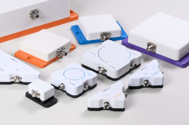
Antenna couplers are designed for measurement purposes and operate in close proximity or direct contact with the DUT. They support wideband operation at the cost of VSWR performance (typically VSWR ≤ 2.0, return loss ≤ –10 dB). The antenna coupler (Fig. 1) is suitable for both transmission and reception testing, and is an effective device for interconnect evaluation.
The primary advantage of the antenna coupler is its ability to achieve an EVM (Error Vector Magnitude) of less than 1% when the coupler is engaged during OTA testing. The EVM represents the modulation accuracy of a digitally modulated signal; when the EVM deteriorates, the constellation points become distorted—as shown in Fig. 2 due to amplitude and phase errors—and in the worst case, interconnect testing may fail to establish communication.
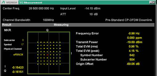
Millimeter-wave radar, 5G communication, and 6G communication systems require interconnect testing in the millimeter-wave band, where the signal bandwidth is extremely wide and the number of modulation symbols is large. If abrupt amplitude or phase variations occur within the band, the constellation points become distorted, resulting in degraded EVM performance.
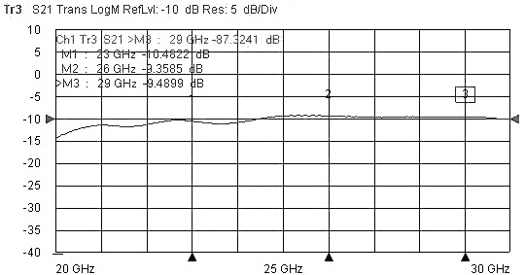
Morita Tech’s millimeter-wave antenna couplers maintain modulation accuracy while enabling high-quality communication with the device under test. Because the coupler achieves an EVM of less than 1% under OTA test conditions, the coupling characteristics measured using a network analyzer—specifically the S21 transmission response in the coupler-to-coupler configuration—become flattened, as shown in Fig. 3.
Furthermore, within a 6 GHz bandwidth, the in-band variation remains within 5 dB, demonstrating that even in OTA testing with opposing antenna couplers, the system exhibits characteristics comparable to those obtained with direct cable coupling.
OTA Measurement Using Antenna Couplers
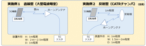
The 3rd Generation Partnership Project (3GPP) has proposed several recommended methods for millimeter-wave OTA measurements. For example, as shown in Fig. 4, the 5G OTA measurement approach employs horn antennas and is fundamentally based on far-field measurement. Measurement-instrument vendors also provide OTA test systems derived from this method. However, the far-field OTA configuration using horn antennas presents a significant drawback: the device under test must be placed several meters away from the antenna, resulting in a large and bulky OTA test setup.
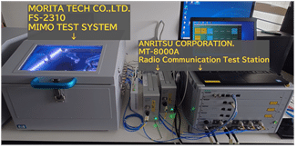
By using an antenna coupler, the challenges associated with millimeter-wave over-the-air (OTA) coupling tests can be dramatically improved. As shown in Figs. 5 and 6, combining a compact shield box with the antenna coupler enables the construction of a desktop-sized OTA test environment. This configuration can be easily deployed and supports various production scenarios, including development, prototyping, and mass-production line setup.
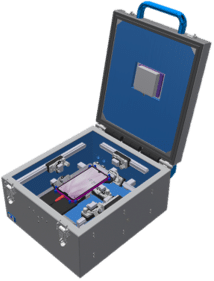
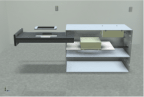
The antenna coupler can also be used for millimeter-wave MIMO (Multiple Input Multiple Output) OTA testing. When integrated into a compact shield box, the MIMO-specific antenna coupler enables easy measurement of maximum throughput during MIMO connectivity tests. It also supports Carrier Aggregation (CA) testing.
Morita Tech’s shield boxes provide wideband shielding performance from 600 MHz to 100 GHz, with an isolation level exceeding 60 dB. This allows OTA testing of modules and terminals not only for LTE, FR1, and FR2 bands, but also for millimeter-wave radar and next-generation FR3 communication systems. By simply replacing the antenna coupler, various devices can be evaluated over-the-air with minimal setup changes.
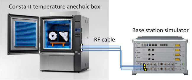
By using an antenna coupler, OTA testing inside a temperature chamber—something difficult to achieve with conventional far-field OTA methods using horn antennas—can be performed easily. OTA evaluation can be conducted across a temperature range from −10 °C to +55 °C.
Millimeter-Wave Electromagnetic-Field Visualization
Millimeter-wave radar estimates distance, velocity, and angle by analyzing the signals reflected from a target. Visualizing these electromagnetic waves enables intuitive understanding of where the transmitted waves propagate and what the radar detects. However, because millimeter-wave signals have extremely short wavelengths, high measurement accuracy is required. Moreover, three-dimensional spatial measurement demands the combination of a high-precision millimeter-wave measurement instrument and a high-accuracy 3D electromagnetic-field visualization system.
Morita Tech offers two types of electromagnetic-wave visualization systems capable of displaying the spatial distribution of millimeter-wave radar emissions in three dimensions.
1. 3D Spatial Electromagnetic-Wave Visualization System
Model: WM9500 Series
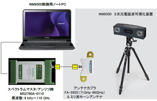
Morita Tech’s 3D spatial electromagnetic-field visualization system detects the XYZ position of a handheld coordinate sensor using infrared signals from a motion-capture camera integrated into the main unit. This enables three-dimensional measurement of electromagnetic waves radiated from the device under test. Electromagnetic-wave measurements can be performed easily using a horn antenna or sensor already available to the user.
By allowing arbitrary selection of measurement points in space, the system provides significantly greater flexibility compared with conventional electromagnetic-wave measurement systems. It supports visualization of electromagnetic waves from 10 Hz to 110 GHz, including the millimeter-wave band.
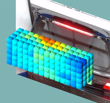
The system enables intuitive visualization of radiation patterns from millimeter-wave radar modules installed in vehicles, as well as attenuation characteristics caused by vehicle bumpers.
2. High-Precision Spatial Electromagnetic-Wave Visualization System
Model: WM9000
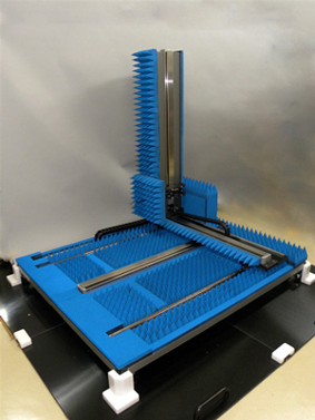
Morita Tech’s WM9000 electromagnetic-wave visualization system offers multiple measurement modes and can accommodate a wide variety of test objects. It enables high-accuracy measurement of electromagnetic waves radiated from large equipment. The system can precisely capture millimeter-wave radiation patterns emitted from mobile phones, wireless devices, and vehicles, as well as electromagnetic emissions from large displays and household appliances.
The measurement range is 1000 mm × 1000 mm × 1000 mm along the X, Y, and Z axes, with a position resolution of ±0.01 mm on all axes, providing extremely high-precision spatial visualization. Electromagnetic-wave distribution within the measurement volume can be visualized at a 1 mm pitch across all axes.
Conclusion
This paper has outlined the challenges and complexities associated with OTA measurements for various millimeter-wave communication modules, as well as the inherent difficulty of visualizing millimeter-wave electromagnetic fields. In the telecommunications industry, it is evident that higher-frequency bands—such as millimeter-wave and sub-terahertz—will continue to be adopted and reallocated to accommodate rapidly increasing data traffic. In particular, during the 6G era, the current 5G frequency bands are expected to become insufficient in capacity, making the acquisition and efficient utilization of new spectrum indispensable. Consequently, further increases in operating frequencies are anticipated as communication demands continue to grow.
In this context, Morita Tech’s antenna-coupler technology and 3D spatial electromagnetic-wave visualization systems will play an essential role in product development, millimeter-wave radar evaluation, terminal testing, and production-line inspection for devices equipped with millimeter-wave modules.
References:
- A. Saeki, “Three–Dimensional Electromagnetic Field Visualization System,”
Contributed article in the Journal of the Institute of Information and Communication Engineers, April 30, 2024, Tokyo (Shinagawa), Japan. (in Japanese) - A. Saeki and J. Minejima, “Near–Field OTA Measurement Using Antenna Couplers,”
ETSI TC ERM Meeting #89, Contribution Document ERM (26)89045, Sophia Antipolis, France, June 2026. (Unpublished conference contribution)
By Akinori Alex Saeki, Director and Head of Sales, Morita Tech Co., Ltd. He is an Executive leader in technical sales for telecom, RF, and EMC fields. Drives Morita Tech’s global business development, customer engagement, and advanced technical proposal activities.