




Building a Multi-Sensor Monitoring Platform on the Infineon PSOC™ Edge E84

Note: This project is an engineering demonstration built on an evaluation platform. It is not a medical device. Its outputs have not been clinically validated and must not be used to determine whether an infant is breathing, present, or safe. The system does not replace caregiver supervision or established safe-sleep practices.

Modern baby monitors are expected to do more than stream audio or video; consumers now expect functions such as connected monitoring, real-time alerts, and child-safety features. The global smart baby monitor market was estimated at US$1.35 billion in 2022 and is projected to reach about US$2.48 billion by 2030, reflecting growing demand for these improvements.[1] At the same time, infant monitoring must be viewed in the context of established safe-sleep guidance. The American Academy of Pediatrics recommends that infants sleep on their backs, on a flat, non-inclined surface, in an uncluttered sleep space, and in the parents’ room on a separate infant sleep surface for at least the first six months.[2]
This project explores how an embedded system can support a baby-monitoring experience by providing local awareness, useful context, and automated feedback without depending on a cloud connection or external computer. The broader shift toward edge artificial intelligence (AI) supports this direction, with the global edge AI market valued at approximately US$24.91 billion in 2025 and projected to reach US$118.69 billion by 2033, driven by demand for low-latency processing, Internet of Things (IoT) expansion, and privacy-focused local intelligence.[3] Building that kind of monitor requires more than adding a camera or microphone; it requires integrating video, motion sensing, audio classification, and real-time user feedback into a single reliable embedded system.
This guide documents the design, coding, and building of an edge-AI baby-monitoring prototype based on the Infineon PSOC Edge E84 AI Evaluation Kit (KIT_PSE84_AI) development board. The system combines a local display interface, live camera preview, 60GHz radar-based motion detection, audio playback, and on-device baby-cry classification to demonstrate how multiple sensing modalities can work together in a practical monitoring workflow.
Starting from Infineon’s open-source PSOC_Edge_Graphics_LVGL_Demo, each subsystem is enabled in sequence:
- 4.3-inch MIPI DSI display
- USB camera feed streamed to the display
- Time-division multiplexing (TDM) audio playback through a TLV320DAC3100 codec and speaker
- XENSIV™ BGT60TRxx 60GHz radar motion detection
- LiteRT for Microcontrollers model for baby-cry classification running on an Arm® Ethos™-U55 neural processing unit (NPU)
A rule-based song-auto-play algorithm ties the sensors together: 1) three detected cries within five minutes, or 2) eight seconds of sustained radar agitation, automatically triggers song playback.
In addition to building and testing the final demonstration, this guide focuses on the engineering details required to make the system work reliably. It covers the wiring, firmware configuration, integration steps, and debug issues encountered for each subsystem, including the observed symptoms, root causes, and code or configuration changes that resolve them.
Project Materials and Resources
Project Bill of Materials (BOM)
- Infineon KIT_PSE84_AI PSOC™ Edge E84 AI evaluation kit
- 4.3-inch MIPI DSI LCD, 800×480 IPS, capacitive touch, with 15-pin DSI ribbon and 4-pin power/I²C cables
- 4Ω/3W passive speaker with bare wire leads
- Molex PicoBlade header and crimp housing
- Molex PicoBlade 1.25mm two-position right-angle SMT header (Mouser # 538-53261-0271)
- Molex PicoBlade two-position crimp housing (Mouser # 538-51021-0200)
- 15-pin 0.5mm pitch flat flex cable (FFC) for the DSI link
- Soldering iron, solder, crimp tool
- Windows 11 development PC
- USB Type-C cable for programming, UART debug, and power (5V/500mA minimum)
Project Code/Software
- GitHub Repository
- Infineon ModusToolbox 3.x with GCC Arm toolchain and Device Configurator (developed with ModusToolbox tools 3.7, Device Configurator 5.60, and GCC 14.2.1)
- PSOC_Edge_Graphics_LVGL_Demo base project
- audio-codec-tlv320dac3100 driver library
- emusb-host middleware with the USB video class driver
- DEEPCRAFT™ babycry model library (babycry_lib_eval.a)
- Python 3.x and FFmpeg
- Tera Term or similar terminal emulator
Project Technology Overview
The PSOC Edge E84 microcontroller integrates three processors: an Arm Cortex®-M33 core for security and system management, an Arm Cortex-M55 that runs the application, and an Arm Ethos-U55 NPU that runs neural network inference, removing that task from the central processing unit (CPU). The kit includes several peripherals; in this build, we used the 64MB flash, display controller and 2D graphics processing unit (GPU), digital microphones, audio codec, 60GHz radar, and USB host port (Figure 1). The firmware is a three-project ModusToolbox workspace (proj_cm33_s, proj_cm33_ns, proj_cm55); everything in this guide runs on the CM55 under FreeRTOS.
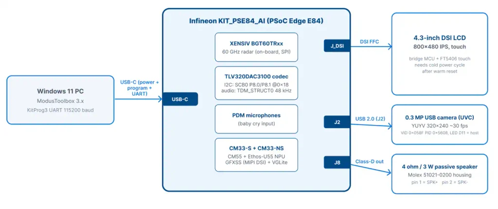
The project covers the following tasks:
- Solder the J8 speaker connector, attach a cable to the display, and connect the USB camera to J2.
- Expand the CM55 flash partition from 2.75MB to 6MB to make room for the audio files.
- Configure the build for the 4.3-inch display and add the codec, radar, ML, and emUSB-Host libraries.
- Generate 48kHz pulse-code modulation (PCM) audio assets from MP3 files with Python and FFmpeg.
- Build, program, and verify each subsystem in sequence: display and user interface (UI), camera, audio, cry detection, and radar.
- Enable the song auto-play state machine that ties all the sensors together.
- Diagnose documented issues.
Hardware Overview
PSOC Edge E84 (KIT_PSE84_AI)
The Infineon PSOC Edge E84 AI Kit is a ready-to-use development platform for exploring edge AI applications. It combines the PSOC Edge E84 microcontroller with a camera, microphones, motion and environmental sensors, 60GHz radar, and Wi-Fi and Bluetooth® connectivity, enabling developers to quickly test applications involving vision, voice, motion sensing, and local AI processing. The kit (Figure 2) comes with pre-programmed demos and connects to a PC through USB Type-C, making it easy to power up, select an application, and begin experimenting without building the hardware from scratch.
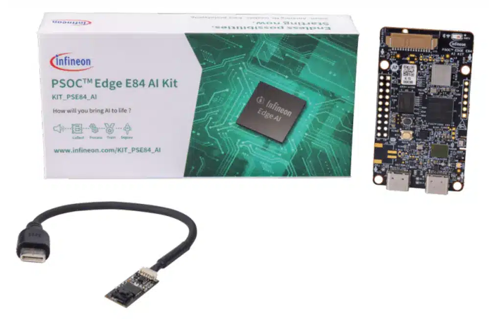
4.3-inch MIPI DSI Touch Display
The display is an 800×480 touch panel with a bridge microcontroller (MCU) that translates the MIPI DSI video stream into panel signals. A single 15-pin flat flex cable to J_DSI carries video. The board support package (BSP) includes drivers for this panel through the W4P3INCH_DISP build target.
0.3 MP USB Camera Module (UVC)
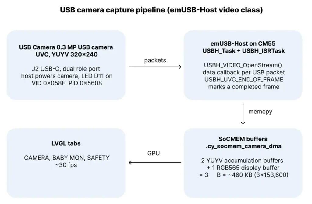
The 0.3MP USB camera module is a standard USB Video Class (UVC) webcam that streams uncompressed YUYV frames at 320×240 and about 30 fps. It connects to the USB Type-C device/host connector (J2), which is a dual-role port: Attaching the camera switches it to host mode, powers the camera, and lights LED D11. The firmware enumerates the camera over USB; no wiring, pin mapping, or I²C setup is involved.
XENSIV BGT60TRxx Radar
The XENSIV BGT60TRxx 60GHz radar is soldered to the board, so no wiring is required. It communicates over serial peripheral interface (SPI), detects motion (even in darkness), and provides presence and breathing indicators on the SAFETY tab in the graphical user interface (GUI). It complements the microphone by detecting restlessness before crying begins.
TLV320DAC3100 Audio Codec and Speaker
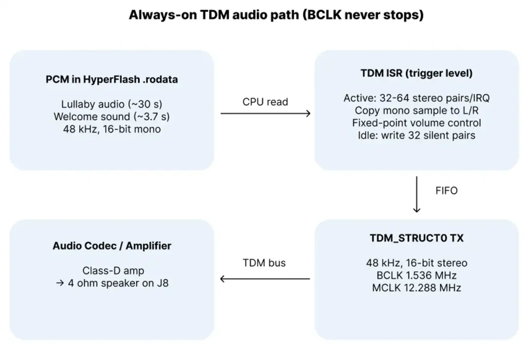
The Texas Instruments TLV320DAC3100 converts digital audio into speaker output and is already on the board. It has two connections: a control channel (I²C on SCB0, address 0x18) and a data channel (TDM, a serial audio bus similar to I²S) streaming samples at 48kHz. The speaker connects to J8, an unpopulated footprint that requires soldering.
Software Overview
Six software layers make up the firmware.
ModusToolbox and the Peripheral Driver Library (PDL)
ModusToolbox is Infineon’s build system; its Device Configurator sets up pins, clocks, and memory layout, and generates the corresponding C files and linker scripts.
FreeRTOS
FreeRTOS runs each subsystem (e.g., graphics, camera, radar, cry detection, watchdog) as its own task, so no subsystem blocks another.
LVGL v9
LVGL renders the UI into two frame buffers in the PSOC Edge E84 device’s internal RAM (called SoCMEM), drawing the next frame while the display shows the current one.
emUSB-Host and the USB Video Class
The USB camera is driven by the emusb-host middleware, whose video class driver exposes the USBH_VIDEO API. The stack runs on the CM55 as two FreeRTOS tasks (USBH_Task and USBH_ISRTask) created by the camera task. When attached, the application matches the vendor and product IDs, selects the uncompressed 320×240 mode, and opens a stream; a callback delivers the video data packet by packet. The BSP already configures the USB block, so no changes to the Device Configurator are needed.
LiteRT for Microcontrollers and the Ethos-U55 NPU
The cry detector is a pre-trained Infineon DEEPCRAFT™ model shipped as a compiled library (babycry_lib_eval.a) that LiteRT for Microcontrollers runs on the Ethos-U55 NPU. The NPU requires a scratch block called the tensor arena, and per the memory rule, both the model and the arena must reside in SoCMEM.
Python 3 and FFmpeg (Audio Asset Pipeline)
The song and startup chime begin as MP3 files. Instead of decoding them on the microcontroller, which can cause crashes, the regen_audio_48k.py script uses FFmpeg to convert them on a PC into uncompressed PCM audio samples.
Developing the Project
Project development consists of three phases—assembling the hardware, expanding the flash partition, and configuring the firmware—that must be completed in order.
Note: The build will not fit unless the flash partition has been expanded.
Assembling and Wiring the Hardware
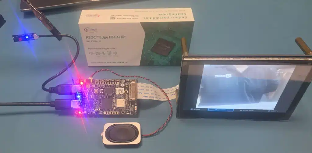
Solder the speaker connector before continuing. If it is missing, the speaker will not work, but the system will not report an error. Figure 3 shows the powered board with the LCD, camera, and speaker connected.
Step 1: Solder the Speaker Connector (J8)
- Locate J8, the two-pad surface-mount footprint for the speaker connector (SPK) near the audio codec.
- Solder the Molex PicoBlade 1.25mm right-angle header onto J8.
- Crimp the speaker leads into the PicoBlade housing, then plug the housing into the header soldered onto J8.
Step 2: Connect the DSI Flat Flex Cable
- Open the zero-insertion-force (ZIF) latch on J_DSI, insert the 15-pin FFC with the metal contacts facing the board, and close the latch.
- Connect the other end to the display’s DSI input the same way, with the stiffener strip facing away from the contacts.
Step 3: Connect the USB Camera (J2)
- Connect the 0.3MP USB camera module to the USB Type-C connector (J2) with the supplied cable. No soldering or pin mapping is required.
- Verify that LED D11 turns on when the camera is attached; the LED indicates that the port has switched to host mode and is powering the camera.
Step 4: Power and Programming
- Connect the USB Type-C cable to the PC. The on-board KitProg3 debugger appears as a COM port that handles both flashing and 115200-baud debug output.
- Ensure the power LED lights.
Expanding the CM55 Flash Partition
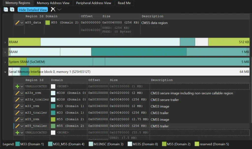
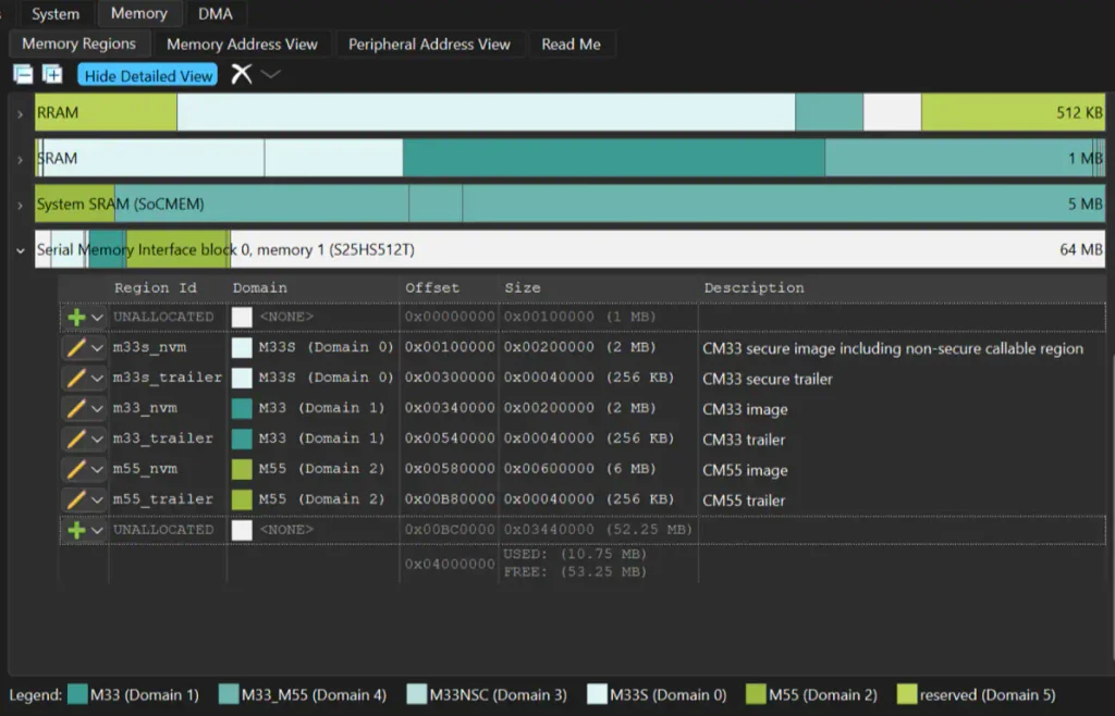
The 64MB flash is divided into partitions, one per core, and the stock demo allocates only 2.75MB to the CM55 application. This build needs about 5.4MB, most of it audio, because raw PCM is large (the 30-second song alone is 2.88MB). Partitions are settings within the Device Configurator, not hardware limits. About 55MB of the chip remains unused immediately after the CM55 slot, so the partition can simply be extended (Figure 4).
- Open the Device Configurator and click the Memory tab.
- Change the m55_nvm length from 0x2C0000 (2.75MB) to 0x600000 (6MB). Do not alter the CM33 partitions; they sit before CM55 in the address map and are unaffected.
- Change the m55_trailer offset from 0x00840000 to 0x00B80000, the new end of m55_nvm (0x00580000 + 0x00600000). Leave its size at 0x00040000. Check this value even if the Device Configurator appears to update it. If the trailer remains at the old offset, it overlaps the expanded m55_nvm region and the Device Configurator reports an error.
- Click Save, and then click Generate. This rewrites the linker script (cymem_gnu_CM55_0.ld) and related headers.
- Rebuild all three projects and reflash; the CM33 code references only the start address of CM55 (0x60580000), not its size.
Configuring the Firmware
Base Project and Display Target
- Clone version 2.3.0 (tag release-v2.3.0) of Infineon’s PSOC_Edge_Graphics_LVGL_Demo (GitHub: mtb-example-psoc-edge-gfx-lvgl-demo) and open it in ModusToolbox; three projects appear. Version 2.6.x uses LVGL v9.5.0 and a different folder layout, so the steps in this guide do not apply to it unchanged.
- In common.mk (application root), set the 4.3-inch panel:
CONFIG_DISPLAY = W4P3INCH_DISP
proj_cm55/Makefile reads this value and selects the correct display and touch drivers
(MTB_DISPLAY_W4P3INCH_RPI, MTB_CTP_FT5406). - Run make getlibs in each project directory to download the middleware.
- In Device Configurator, enable SCB0 as an I²C master (1.8V, 400kHz, P8.0 = SCL, P8.1 = SDA). For its clock, select 16-bit divider 0 (CYBSP_I2C_CONTROLLER_CLK_DIV), which SCB5 also uses for the display. Do not change the divider value (32); doing so also changes the display’s I²C speed. Instead, enable Manual data rate control and set Low phase duty cycle to 5 and High phase duty cycle to 3 (about 390kHz). Confirm the Notices pane shows no errors, then click Generate.
Add the Codec, Radar, ML, and USB Camera Libraries to the Build
Append the following to proj_cm55/Makefile:
# audio codec + radar driver sources
SOURCES += ../mtb_shared/release-v2.0.0/xensiv_bgt60trxx.c \
../mtb_shared/release-v2.0.0/xensiv_bgt60trxx_mtb.c \
../mtb_shared/release-v2.0.0/xensiv_bgt60trxx_edge.c \
../audio-codec-tlv320dac3100/mtb_tlv320dac3100.c
INCLUDES += ../audio-codec-tlv320dac3100
# DEEPCRAFT babycry model on the Ethos-U55
COMPONENTS += ML_TFLM ML_FLOAT32 ML_INT8x8 CMSIS_DSP U55
DEFINES += CY_ML_MODEL_MEM=.cy_socmem_data CY_ML_ARENA_MEM=.cy_socmem_data
LDLIBS +=
./ready_models/CONFIG_$(CONFIG)/TOOLCHAIN_$(TOOLCHAIN)/babycry_lib_eval.a
# USB camera: emUSB-Host video class (kit rev *A)
COMPONENTS += USBH USBH_BASE
CY_IGNORE += ./driver/camera/mtb_dvp_camera_ov7675.c
The CY_ML_MODEL_MEM and CY_ML_ARENA_MEM definitions in the preceding code place the model and tensor arena in SoCMEM because the NPU cannot access external PSRAM.
For the USB camera, also create proj_cm55/deps/emusb-host.mtb, containing the line mtb://emusb-host#release-v2.2.0#$$ASSET_REPO$$/emusb-host/release-v2.2.0, and then rerun make getlibs.
Generate the Audio PCM Assets
The generated audio files (proj_cm55/lullaby_data.c and proj_cm55/welcome_sound_data.c) are included in our GitHub repository, so this step is needed only to replace the audio with your own MP3 files.
- Download regen_audio_48k.py, [your_children_song].mp3, and [your_welcome_sound].mp3 from the root of our GitHub repository and place them in the project root (the folder that contains proj_cm55).
- Install FFmpeg, ensure it is on the system PATH, and confirm the correct file names are used.
- From the project root, run python regen_audio_48k.py.
This script converts the song to 48kHz mono PCM, trims it to 30 seconds (1,440,000 samples, ~2.88MB), and writes proj_cm55/lullaby_data.c. The boot chime is converted the same way with loudness normalization (welcome_sound_data.c, 3.71s).
Project File Structure and Code Reference
This build adds the baby monitor feature set on top of Infineon’s demo inside proj_cm55, which is the only project this guide modifies (proj_cm33_s and proj_cm33_ns are used unmodified). In total, 24 files were created or modified, plus one Python helper script at the repository root. Of those 24, 13 are new subsystem modules written specifically for this build (camera capture, radar processing, the touch UI, cry detection, song playback, the audio driver, the boot screen, and their supporting data and config files), five are edits to files that ship with the base demo (CM55 Makefile, main.c, FreeRTOS hooks, fault handler, and Rutronik radar driver), one is a one-line patch inside a third-party library (minimp3.h), and four are earlier-generation files. These five are kept for reference in our repository’s superseded_not_in_build folder and are not part of the build. Table 1 maps each to its function and purpose.
Table 1. Every file created or modified for this project, grouped by role
| File | Status | Purpose |
|---|---|---|
| camera_sensor.c/.h | New | USB (UVC) camera capture task; converts YUYV frames to RGB565 in SoCMEM for the GPU (kit rev *A). |
| radar_sensor.c/.h | New | BGT60TR13C signal processing: range-gated magnitude, motion, presence, and the breathing bandpass filter. |
| radar_ui.c/.h | New | LVGL touch dashboard: the RADAR, CAMERA, BABY MON, and SAFETY tabs, including the SAFETY privacy gate. |
| cry_detector.c/.h | New | Captures pulse-density modulation (PDM) microphone audio and runs the DEEPCRAFT babycry model via LiteRT for Microcontrollers on the Ethos-U55 NPU. |
| lullaby_player.c/.h | New | Multi-sensor song state machine (cry-count and motion triggers, calm-based auto-stop) and playback control. |
| buzzer.c/.h | New | Interrupt-driven TDM/I²S audio driver; always-on bit clock, tone mode, and PCM playback mode. |
| boot_screen.c/.h | New | Full-screen Mouser boot overlay and the timer that synchronizes it with the welcome chime. |
| lullaby_data.c/.h | New (generated) | 48kHz PCM sample array for the song, produced by regen_audio_48k.py. Required for the build to link. |
| welcome_sound_data.c/.h | New (generated) | 48kHz PCM sample array for the boot chime, produced by regen_audio_48k.py. Required for the build to link. |
| mouser_logo_data.c/.h | New | Mouser logo bitmap asset placed in SoCMEM so the GPU can read it. |
| sys_monitor.c/.h | New | FreeRTOS heap and tick resource-monitor task used while debugging stack and heap pressure. |
| debug_diag.c/.h | New | Stack overflow and memory allocation (malloc) failure FreeRTOS hook bodies; prints the failing task name to the serial console. |
| display_i2c_config.h | New | Pin and clock definitions |
| main.c | Modified | Base demo entry point; wired up to create the camera, radar, cry-detection, song, and sys-monitor tasks and to init SCB0 I²C for the codec. |
| Makefile (proj_cm55) | Modified | Adds SOURCES, COMPONENTS, DEFINES, and LDLIBS for the codec, radar, ML/Ethos-U55, and USB camera libraries (see Software Setup, above). |
| freertos_hooks.c | Modified | Stack overflow and malloc failure hook implementations routed through debug_diag.c. |
| fault_handler.c | Modified | Dumps the CFSR fault status register on HardFault/BusFault; used to diagnose the direct memory access (DMA) and flash-window faults documented later. |
| driver/radar/radar.c/.hradar_settings.h | Modified | Rutronik reference BGT60TR13C driver, adapted to this board’s SPI wiring and settings. |
| minimp3.h | Patched (third-party) | In superseded_not_in_build/; not used in the build. |
| lullaby_mp3_data.c/.h | Superseded | Original on-chip MP3 byte array. Replaced by lullaby_data.c once pre-converted PCM proved simpler and lighter on CPU; kept for reference only. In superseded_not_in_build/; not used in the build. |
| face_detector.c/.h | Superseded/disabled | Experimental Infineon ifx_face_id integration. Disabled after its psram_init() call corrupted the camera DMA path. In superseded_not_in_build/; not used in the build. |
| psram_init.c/.h | Superseded/disabled | PSRAM (SMIF) bring-up added to support the face-ID experiment. In superseded_not_in_build/; not used in the build. |
| driver/camera/mtb_dvp_camera_ov7675.c/.h | Legacy (pre rev *A) | DVP camera driver for kits before revision *A. Excluded from the rev *A build via CY_IGNORE in the Makefile; needed only on earlier kit revisions. |
| regen_audio_48k.py (repo root) | New (PC tool) | PC-side FFmpeg pipeline that converts source MP3 files into the PCM arrays in lullaby_data.c and welcome_sound_data.c. Not compiled into the firmware. |
The complete, buildable source described in this guide, including every file in Table 1, is published on Mouser’s GitHub. Clone it directly rather than reassembling the project from this document if a working starting point is preferred.
Executing the Project
Build and flash from the Eclipse-based ModusToolbox integrated development environment (IDE). First, import the application and click Build Application. This compiles the three projects (CM33-S, CM33-NS, CM55) in order. Then, flash with the Program (KitProg3) launch configuration.
The command line equivalent is:
make build -j8 CONFIG=Debug TARGET=APP_KIT_PSE84_AI
make program
Open a serial terminal on the KitProg3 COM port at 115200 baud, then bring up each subsystem in the order listed in Table 2.
Table 2. Peripheral bus and pin assignments used in this project
| TLV320DAC3100 control | I²C (SCB0) | P8.0 = SCL, P8.1 = SDA (1.8V) | 0x18 @ 400kHz |
| TLV320DAC3100 audio | TDM (TDM_STRUCT0) | BSP TDM pins | 48kHz 16-bit stereo |
| Display video | MIPI DSI (GFXSS) | J_DSI, 15-pin FFC | 800×480 |
| USB camera (UVC) | USB 2.0 host (emUSB-Host) | J2 USB Type-C dual role port; LED D11 = host mode | YUYV 320×240 @ ~30 fps |
| BGT60TRxx radar | SPI | on-board | polled every 100ms |
| Speaker | Class-D analog | J8 (two-pin speaker connector) | 4Ω/3W |
The repository also includes the combined firmware image from this build (prebuilt_firmware/app_combined.hex) for readers who want to load the demo without building it.
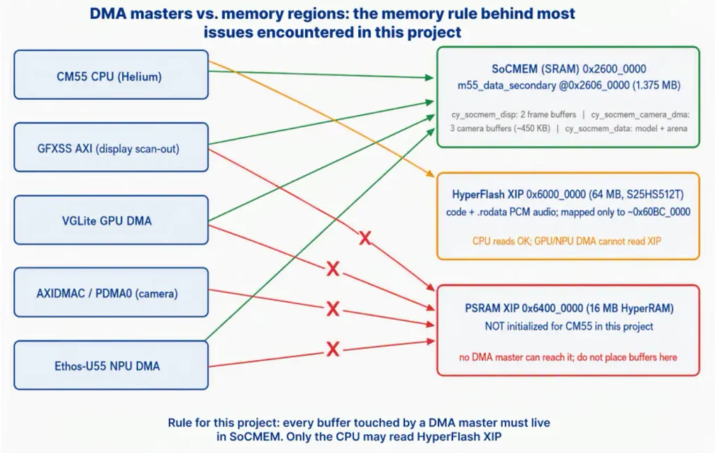
One architectural detail worth noting for this project is that three blocks on this chip move data without CPU involvement: the display scan-out, the GPU, and the NPU. In our project, these DMA masters can access only the chip’s SoCMEM. They cannot access the external PSRAM or read the flash. Only the CPU reads flash directly, through XIP (execute-in-place, which maps flash into the address space like ROM). This leads to the memory rule that governs the whole project: Any buffer accessed by DMA hardware must be placed in SoCMEM (Figure 5). Ignoring this can result in a black screen, corrupted data, or a hard fault, with no clear indication of the cause.
Boot Sequence and Welcome Sound
At power-up, the secure core completes its setup, the non-secure CM33 releases the CM55, and FreeRTOS starts. A five-second boot screen plays while the system initializes (Figure 6); a Mouser wordmark fades in at 200ms, and a timer starts the welcome chime at the same moment. The chime doubles as a hardware test: If it plays, the codec, TDM link, and speaker wiring are all operating as intended.
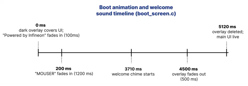
In this project, the GPU cannot access images stored in CPU memory or flash. As a result, the CPU draws the boot-screen text directly, whereas bitmap assets, such as logos, must be placed in SoCMEM before the GPU can render them.
Display Bring-Up and the LVGL UI
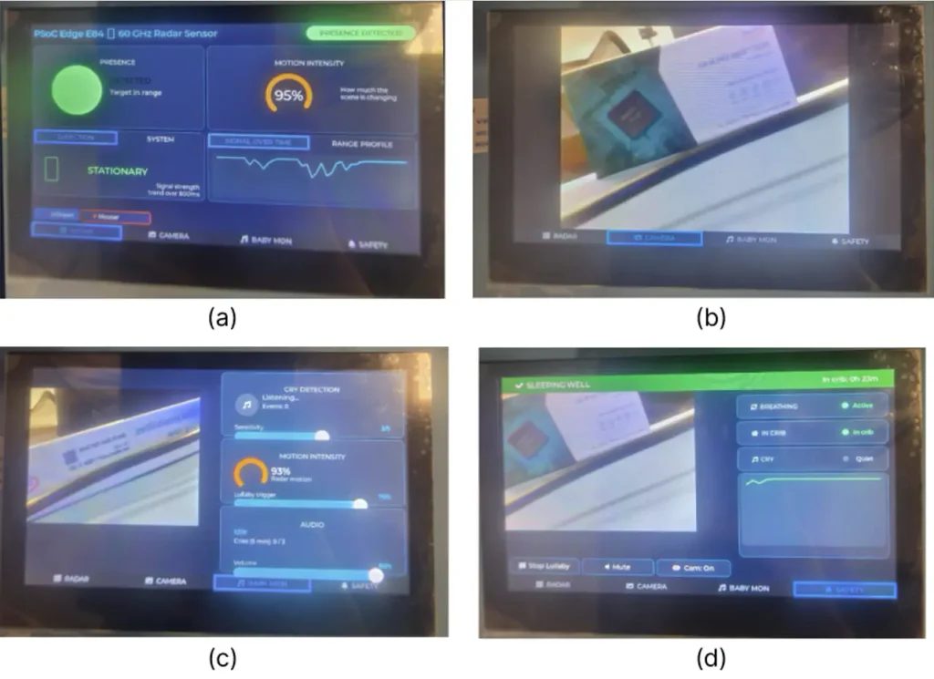
After the boot screen fades, LVGL brings up a four-tab touch UI (Figure 7): RADAR (signal charts), CAMERA (full-screen live view), BABY MON (a 400×300 camera view, plus CRY DETECTION, MOTION INTENSITY, and AUDIO panels), and SAFETY (a 480×360 camera view, breathing and crib-presence chips, and Play Lullaby, Mute, and Cam buttons). On the SAFETY tab, the camera feed is privacy-gated, hidden until the baby cries or breathing is not confirmed. The feed is visible for 10 seconds after the alert clears, with the Cam button forcing it on when needed.
Live USB Camera Preview
The pipeline (Figure 8) is event-driven. The video callback copies each incoming USB packet into one of two YUYV accumulation buffers in SoCMEM. At the end of each frame, the camera task converts the completed frame to RGB565 using integer BT.601 math, which takes about 2ms, cleans the D-cache so the GPU reads coherent pixel data, and publishes the frame to the UI. The system also handles camera disconnections. If the camera is unplugged and reconnected while the system is running, the task waits for the USB device to be detected again before resuming streaming. On first boot, watch the serial port for “[Camera] USB camera streaming” and the one-time “[Cam] First USB frame!” message; non-zero bytes confirm pixel data is flowing.
Debugging: HardFault from DMA-Inaccessible Buffers
Symptom: An imprecise (CFSR = 0x00000400) hard fault during camera startup, meaning the CPU cannot report which access failed.
Cause: Two layers. A face-recognition experiment had added a psram_init() call that corrupted PSRAM access. Removing it exposed the second layer: One camera buffer remained in a PSRAM linker section, so the first memset() wrote to an unmapped address range.
Fix: Move all camera buffers into SoCMEM and remove all PSRAM use from the CM55 (Table 3). The three QVGA buffers use about 450KB of the 1.375MB SoCMEM region.
Table 3. Buffer placement rules that keep every DMA master operational
| Buffer | Linker section | Region | Why |
|---|---|---|---|
| LVGL frame buffers (×2) | .cy_socmem_disp (NOLOAD) | SoCMEM | Display scan-out cannot read PSRAM |
| USB YUYV accumulation (×2) | .cy_socmem_camera_dma (NOLOAD) | SoCMEM | Filled per USB packet in USBH task context |
| Camera RGB565 display buffer | .cy_socmem_camera_dma (NOLOAD) | SoCMEM | Converted by CPU, drawn by GPU |
| babycry model + tensor arena | .cy_socmem_data | SoCMEM | NPU DMA cannot read PSRAM |
| PCM audio (song, chime) | default .rodata | HyperFlash XIP | Only the CPU reads it, inside the TDM interrupt |
| VGLite GPU heap | gfx_mem @ 0x26200000 | SoCMEM | GPU-only region, 3MB |
Speaker Audio Playback
The audio path (Figure 9) is interrupt-driven: The TDM peripheral drains a small FIFO at 48,000 samples per second and interrupts when the level runs low; the handler refills it with the next 32 to 64 samples read directly from the PCM arrays in flash, duplicating mono into both stereo slots and applying volume scaling. CPU flash reads are allowed (the memory rule restricts only DMA hardware), so the audio needs no RAM copy.
Attaining reliable sound requires three debug fixes:
Debugging: TDM Peripheral Not Clocked
Symptom: Complete silence. The codec responds normally over I²C, but the TDM FIFO level remains at zero immediately after data is written.
Cause: Each peripheral is controlled by a clock gate, and the code did not enable the TDM clock. Without a clock, the peripheral does not produce an obvious error; its registers can still be read, but writes have no effect. The code also omitted the EnableTx call required before ActivateTx.
Fix: Add the following three calls at the beginning of buzzer_init(), in the following order:
Cy_SysClk_PeriGroupSlaveInit(CY_MMIO_TDM0_PERI_NR, …); /* open the clock gate */
Cy_AudioTDM_EnableTx(CYBSP_TDM_CONTROLLER_0_TX_HW);
Cy_AudioTDM_ActivateTx(CYBSP_TDM_CONTROLLER_0_TX_HW); /* Enable BEFORE Activate */
Debugging: Shared I²C Clock Divider Conflict
Symptom: After adding the codec driver, the display’s I²C bus begins reporting intermittent errors.
Cause: Device Configurator assigned the codec’s I²C bus and SCB5 to the same clock divider. During codec initialization, mtb_hal_i2c_configure() reconfigured the shared divider, disrupting the timing of the display’s I²C bus.
Fix: Remove the mtb_hal_i2c_configure() call, as the generated configuration already includes the correct settings for both buses. If two otherwise unrelated buses begin malfunctioning simultaneously, determine whether they share a clock divider.
Debugging: Silent Playback After the First Session
Symptom: The startup beep plays, but all subsequent sounds are silent until reboot.
Cause: The driver deactivated TDM after each playback, and stopping TDM also stops BCLK, the clock the codec synchronizes to. The codec loses sync and does not recover.
Fix: Keep the clock running. Buzzer_init() starts TDM exactly once; when idle, the interrupt handler feeds zeros (about 0.03 percent CPU). Play and stop only set flags and never touch the TDM hardware again.
Baby Cry Detection
The cry detector processes audio in half-second windows and passes each to the DEEPCRAFT model on the NPU, which returns a confidence score for crying. A UI sensitivity setting (1–5) sets the threshold; detections are held for two seconds to prevent flicker and time-stamped into a rolling list that the song logic reads. Since the NPU performs inference, the graphics and audio run undisturbed.
Radar Presence and Breathing Detection
The radar task reduces each frame to a range-gated magnitude value, which it uses to estimate signal strength, motion, presence, and breathing activity. Presence detection relies on a state machine with hysteresis and debounce timers. Detection begins when the signal exceeds 60 percent and ends when it falls below 45 percent. This prevents the status from flickering when the signal remains near a single threshold.
To detect breathing, the system isolates changes in the peak reflection magnitude within the approximate 0.1 to 1.5Hz chest-motion range by subtracting a slow baseline from a faster low-pass-filtered signal. A live target produces measurable variation in this range, while a stationary object, such as furniture or a wall, produces no sustained variation. The presence state also requires breathing activity or motion within the previous 15 seconds, preventing a strong but inactive reflection from holding the detection state. Motion alerts are temporarily suppressed during audio playback to prevent the speaker from triggering a new alert.
Debugging: Breathing Shown Active with the Sensor Covered
Symptom: Covering the radar completely still shows BREATHING: Active, and the IN CRIB chip toggles between In crib and Not detected.
Cause: The breathing indicator relied only on reflection strength, allowing stationary objects to be mistaken for breathing activity. Presence detection also used a single 55 percent threshold, causing the presence state to flicker when the signal hovered near that value.
Fix: Replace the reflection-strength check with band-pass life-sign detection, which looks for breathing-like signal variation rather than signal strength alone. Add hysteresis to presence detection so presence begins above 60 percent and ends below 45 percent. To verify the fix, monitor the serial output printed every five seconds:
[Radar] sig= mot= br= life= pres=
Compare the br= value with a person in range and with the sensor covered. If the values do not clearly separate, adjust BREATH_MIN_LVL until breathing activity can be distinguished from a blocked or inactive sensor.
Song Auto-Play Logic
The song state machine combines the sensors. It starts looped playback on one of two triggers: three or more cries within a five-minute window, or motion at 70 percent or higher sustained for eight seconds. It stops when the room remains calm (i.e., no cries, motion below 20 percent) for two full minutes, with a minimum play time of 60 seconds. The SAFETY tab buttons call the same start/stop functions.
Debugging: minimp3 Stack Overflows (Two Consecutive HardFaults)
Symptom: MP3 decoding with minimp3 causes repeated HardFaults. Debugging shows the stack pointer outside the task’s allocated stack region, indicating a stack overflow.
Cause: Multiple large data structures are allocated on the task stack during MP3 decoding.
Fix 1: The decoder state (~6.5KB) and output buffer (~4.5KB) were originally allocated as local variables on an 8KB task stack. Declaring them as static and increasing the task stack size to 16KB resolves the first crash.
Fix 2: A second stack overflow occurs because minimp3.h (line 1718) allocates a ~16KB scratch structure as a local variable during each decode operation. Changing this declaration to static mp3dec_scratch_t resolved the second crash.
Outcome: With both fixes applied, MP3 decoding operates correctly. However, decoding MP3 audio on the microcontroller still consumes significant CPU resources. Converting the audio files to PCM on a PC using FFmpeg and storing the resulting data in flash provides a simpler, more efficient solution, which is the approach used in this project.
Debugging: BusFault at 0x60C00000
Symptom: Placing the 2.88MB song at a manually selected flash address causes a fault on the first read. Debugging shows a BusFault when the application attempted to access address 0x60C00000. The debugger shows that the task stack was still valid, ruling out a stack overflow as the cause of the fault.
Cause: The CPU’s XIP window ends with the CM55 partition, near 0x60BC0000. The selected address exceeded that boundary, pointing to an existing but unmapped flash. Any access to it causes a fault.
Fix: Remove the custom section and linker flag, leaving the array in the standard .rodata section. The partition was previously expanded to 6MB, so the full 5.4MB fits within the mapped window.
Final Results
- Boot chime, looped song, and UI sounds all play reliably; audio survives unlimited play/stop cycles.
- The four-tab UI runs a live 320×240 USB camera preview at ~30 fps (YUYV converted to RGB565 on the CM55); the camera can be unplugged and reconnected without restarting the application.
- Cry detection runs continuously on the NPU; radar motion updates every 100ms.
- Radar presence and breathing indicators remain steady; the SAFETY camera is visible only during alerts or on demand.
- Both song triggers are verified, plus the auto-stop after two calm minutes.
- The application uses approximately 5.4MB of the 6MB CM55 flash partition.
- SoCMEM: ~1.5MB frame buffers + ~450KB camera buffers + model and arena.
Conclusion
This project demonstrates that a single edge-AI microcontroller can support a multi-sensor AI baby monitor prototype. GPU-accelerated graphics, continuous 48kHz audio, radar-based presence and breathing analysis, USB camera streaming, and neural network inference all run concurrently, with the NPU handling the AI model. More importantly, combining microphone, radar, and camera data creates a more reliable monitoring experience because each sensor helps compensate for the limitations of the others. All audio, video, and sensor data is processed locally, providing real-time feedback without sending private information to the cloud.
The completed system still has substantial room to grow, with approximately 52MB of available flash and an idle CM33 core. Future development could add Bluetooth Low Energy or Wi-Fi alerts, event logging, configurable detection thresholds, sensor-fusion confidence scores, additional audio or vision models, and lower-power operating modes. These additions could turn the current prototype into a more adaptive monitoring platform while preserving the project’s core advantages: local intelligence, responsive operation, and privacy by design.
Sources
[1]https://www.grandviewresearch.com/press-release/global-smart-baby-monitor-market
[2]https://publications.aap.org/aapnews/news/20619/New-safe-sleep-recommendations-can-help
[3]https://www.grandviewresearch.com/industry-analysis/edge-ai-market-report
Ricky Flores is a Technical Marketing Engineer at Mouser Electronics. He received a master’s degree in electrical engineering from the University of Michigan and has worked at Texas Instruments and the Center for High Technology Materials (CHTM) at the University of New Mexico. Ricky combines extensive expertise in MEMS, ESD, and analog design engineering with over a decade of experience in technical marketing. Outside of work, he explores interests in real estate, coding, DIYs, and enhancing user experiences for engineering applications.