


Are you experiencing issues with your DC/DC power supply not starting up properly when designing your power supply systems? In this paper, we will sort out the problems of the power supply failing to start or starting improperly, analyze the reasons behind them, and provide solutions.
Table of Contents
Common start-up Failure of DC/DC Converter
The DC/DC power supply is typically installed on the PCB board after the AC/DC power supply. When we usually design and use it, the first concern is whether the power supply can be output normally, and how the load carrying capacity.

However, various problems often arise during testing. The common ones are as follows:
- No output after the power supply is turned on.
- The output keeps hiccupping after the power is turned on, and the system cannot work properly.
When encountering these issues, how should we analyze, confirm, and troubleshoot them? We will now analyze each problem individually.
No Output
There are typically several reasons for “No output” from a power supply.
1. The Input Voltage May be Too High or Too Low
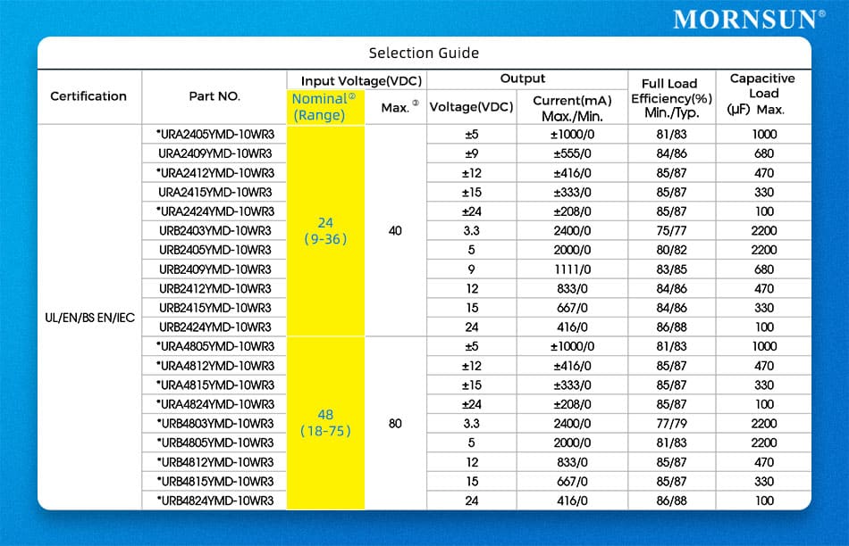
To determine this, use a multimeter to measure the voltage at both ends of the input terminal and compare it to the input voltage range in the data sheet (e.g. 9-36V). If the voltage exceeds the specified range, make the necessary adjustments.
Provide power to the power supply within the input voltage range specified in the datasheet.
2. Insufficient DC/DC Converter Power
To determine this, calculate the actual power of the output load and compare it with the power of the front-end power supply. If the power of the DC/DC converter is not enough, consider replacing it with a higher power one or reducing the load power.
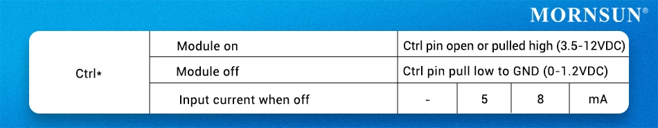
3. The CTRL Function has a Control Logic Error (for the DC/DC power module with CTRL pin)
To determine this, check the control logic of the CTRL pin in its datasheet and test the actual state of the CTRL pin. If it is set incorrectly, follow the instructions in the datasheet to design the CTRL pin and confirm that the control logic is correct.
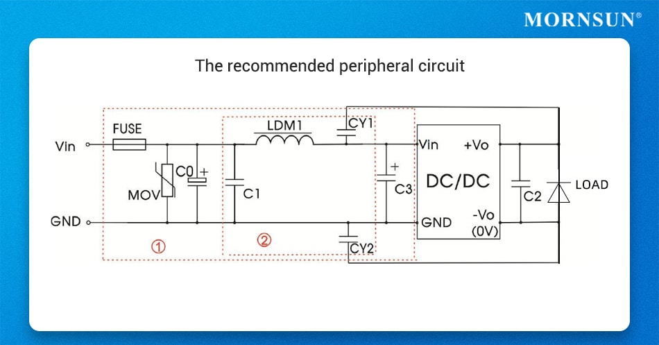
4. Reverse Connection of the Diode in the Peripheral Circuit
The output of the DC/DC power supply is usually connected to electrolytic capacitors, voltage regulator diodes, and other peripheral devices with positive and negative terminals. It is important to avoid reverse connection as it can result in abnormal output.
To determine if the module has an output, test it individually. If the output of the module is normal but becomes abnormal after adding the peripheral circuit, check each peripheral device individually. To solve the issue, correct the polarity of the output devices. and select appropriate specifications.
Furthermore, if the chosen peripheral devices’ specifications do not meet the actual requirements, it may lead to poor output.
Therefore, it is also crucial to confirm that the device’s specifications are appropriate after ruling out a reverse connection.
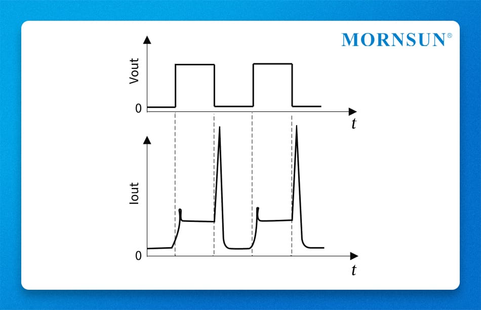
Hiccup Output
Output failure is typically caused by capacitive loads that are too high or by load transient power that exceeds the power supply specifications.
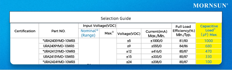
1. Capacitive Load Exceeds Specification
It is important to note that modules with different output voltages have varying capacitive load specifications. To determine whether the capacitance values of all capacitors on the output side of the power supply are within the specification range, it is necessary to check the sum of all capacitance values.
To resolve the issue of exceeding the capacitance specification, adjust the capacitive load or select a power supply that meets the necessary specifications of capacitance load.
2. Excessive Transient Power of the Load (e.g. motor, etc.)
To test the transient load current at the output side, use an oscilloscope and compare it with the power supply overcurrent point. If the start-up current exceeds the overcurrent point, then the DC/DC power module cannot start up normally.
To resolve the issue, it is recommended to either choose a module with higher power or add the soft start processing at the load side to limit the start-up current.
Summary
This paper analyses common start-up problems encountered when using DC/DC power supplies and offers corresponding confirmation methods and solutions to reduce these issues during the design phase.
MORNSUN is a manufacturer of power supply solutions, offering DC/DC converters, AC/DC converters, enclosed AC/DC SMPS, Din-rail AC/DC SMPS for various applications and industries worldwide.
MORNSUN offers a complete range of services, from product research and development to project completion, ensuring that customers receive an optimal solution that combines quality, performance, design, delivery, and after-sales service.
Author: MORNSUN POWER
