Certain doubts in the design of an electronic product can be cleared by building and studying a prototype first. Here we discuss the challenges and different approaches to prototyping.
Prototypes are not just a vital element of the electronics design but a powerful tool for public communication and exhibition too. Creating a physical mock-up of an object makes it possible to understand the ways people will attempt to interact with it, and the ways it can be manipulated. Concisely, in the electronics design and development process, prototypes can be used for different purposes including experimentation, learning, testing, proofing communication and interaction.
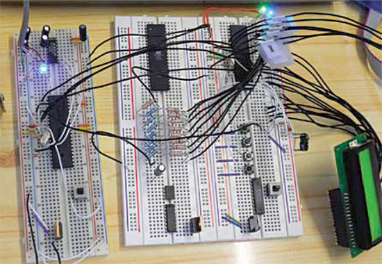
Prototype wiring
Today, designers and DIY practitioners are using various prototyping ideas to express their concepts of electronic artefacts. These prototypes are generally constructed using various solder and/or solder-free methods. All of these methods have their own pros and cons:
Wire-wrapping and point-to-point wiring
In the wire-wrapping method, fie wire is tightly connected to endpoints by wrapping onto a rectangular pin—instead of soldering—with the help of a special gun tool.
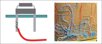
In point-to-point wiring, components are soldered to a perforated board, also known as Vero board.
Both wire wrapping and point-to-point methods are inexpensive, but wire wrapping allows reliable connections to square leads only. So it becomes necessary to solder discrete components to a header that goes into an IC socket or to individual wire-wrap pin. With point-to-point wiring, it is easy to simply twist, solder leads and run wires where needed. However, this method is slow and requires ample skill.
Solderless wiring
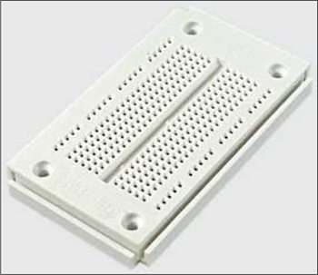
The invention of the solderless breadboard—an improvement over the basic wire-wrapping and point-to-point wiring—was a significant step over many of the other prototyping methods. The breadboard is a quick way to set up any circuit using standard through-hole components. But breadboards are not good for high-frequency circuits due to stray capacitance and inductance. Further, these are not suitable for high-voltage and/or high-current circuits. Although breadboard is an essential facet of the design process, the reliability and endurance of breadboard-based prototypes have been a big problem.
Printed circuit board wiring
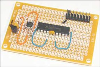
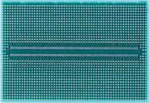
Using a printed circuit board (PCB) is a costlier but reliable method of prototyping electronic circuits. The most common PCB type widely used for hobby prototyping is the generic PCB, which has a pattern of holes and connections (multiple holes per pad) similar to a solderless breadboard.
Generic PCBs are easier to use than plain perforated boards, especially for IC-based circuits. But layout constraints are a minor drawback and prototyping may be much more difficult.
The ‘real’ PCB (which can handle virtually any component and power level) used ubiquitously in the production of electronics is inappropriate for low-budget basic prototyping, because laying out the customised PCB and getting it fabricated may take time. Besides, it is very difficult to make changes or modifications in the initial circuit structure after finishing the prototype.
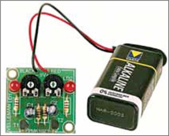
Using surface-mount devices (SMDs) instead of the traditional through-hole components makes a prototype more compact. The PCB layout becomes easier because different things can be done on each side. At the same time, prototyping becomes much more difficult(requires high soldering skill), which calls for the use of special SMD prototyping boards/custom PCBs and handling/soldering tools.
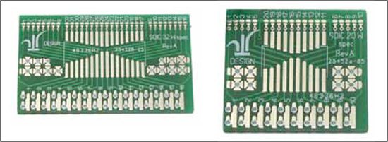
An alternative way to set up the SMD prototype in ‘dead bug’ style is to use special DIP/SIP adaptors that have pads to solder SMD ICs. ‘Surfboards’ with solder pads for connecting larger wires are also available. These make it easy to wire a hybrid electronic circuit (through-hole plus SMD components) on a standard breadboard.
Prototyping difficulties and bugs
Electronics prototypes have many disadvantages and difficulties. Foremost among these is the time taken to build them. It can also be diffcult to estimate the time required to complete a working prototype, particularly because they tend to be non-functional until they are almost complete.
Component selection and circuit design (pre-existing modules, breadboard circuits, custom-designed PCBs, etc) constrain the flexibility of the prototype even as its functioning begins to disclose new possibilities. Another obstacle to adjusting the design of a prototype is that any change risks breaking it completely. This points to one of the other weaknesses of electronics prototypes: their inflexibility and fragility. Electronics prototypes are difficult to transport and maintain. This greatly limits their lifespan and scope.
Another problem with electronics prototypes is the bugs. It is an awkward task to find bugs on a prototype,as there are so many reasons for errors—from wrong wiring of breadboard components, loose connections, broken parts and problems with power supply, to errors in the design concept.
Examples of some bugs to expect are:
- Design/schematic flaws: Poor design concept/drawing error in schematic diagram
- Board layout problem: Wrong/mirror package of the component and/or package conflict
- Assembly errors: Wrong component insertion, i.e., a 100-kilo-ohm resistor used in place of a 10-kilo-ohm resistor
Despite the difficulties, electronics prototypes offer many advantages as a distinctive tool in the design process. Working prototypes are the key to understanding a complex interaction between person and object, and advanced techniques make them a more integrated part of the interaction design process.
Prototype showcasing
It is important to understand the difference between a prototype as part of the design process and a prototype as its outcome. In the former case, it serves as a tool for the designer to reflect upon and refine the interface and object in question. In the latter, it becomes a way for the designer to communicate a concept to a broader audience. As exhibition pieces, however, they require additional time and effort to make them robust and self-reliant.
When it comes to exhibiting (or deploying) electronics designs, the designer needs to move beyond the fragile and delicate breadboard, as it is very difficult to transport breadboard-based prototypes and make them work for portable use. Another problem with breadboard/generic printed circuit board based prototypes is that they are one-offs: Reproduction is expensive, time-consuming and complicated.
One approach to making prototypes more convenient and flexibleis the use of special software such as the Fritzing application for Arduino platform. This allows designers to prepare their electronic inventions for exhibition or production. Simply recreating the tested hardware circuit in software form makes an archivable and shareable file.The shared content includes breadboard, schematics, enclosure and PCB view and may contain additional information such as part ordering numbers. This enables others to interactively scrutinise the electronics design. In effect, the designer creates a robust and long-lasting version of his prototype, close to an end-user product level.
Virtual prototyping?
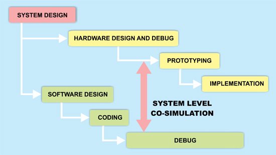
Designing today’s high-end electronic devices is a real challenge, mainly because of the complexity and time-to-market pressure. Most functions of these devices are often grouped into a single integrated circuit, which is then called a system-on-chip (SoC). The design of such systems requires a joint development of custom hardware and software.
The need for faster and better SoC and software development has led to a methodology called ‘virtualised systems development.’ This approach lets designers quickly build virtual prototypes comprising software models of system hardware, drawing upon libraries of fast processor and peripheral models. The result is a high-level model of hardware. By running simulations using these models, systems architects and software developers can perform hardware/software partitioning, develop and debug hardware-dependent code, and start applications software development before any system hardware is actually built.
In a conventional product development process, a physical prototype is usually constructed to prove the design concepts, evaluate design alter-natives, test product manufacturability or just demonstrate the product. But a virtual prototype (or digital mock-up) is a computer simulation of a physical product and the construction. The testing process of a virtual prototype is called virtual prototyping. In summary, virtual prototyping is nothing but an advanced simulation process.
Virtual prototyping is a relatively new technology which calls for the use of virtual reality and other computer technologies to create digital prototypes. It involves the process of simulating in software the user, the product and their combined (physical) interaction through the different stages of product design, plus the quantitative performance analysis of product.
The author is a regular contributor to EFY


