


Logic Gates are the foundation of all digital systems, whether combinational or sequential, the circuit follows some logic.
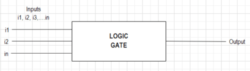
In simple words, a logic gate is a digital circuit with multiple inputs and a single output. The relationship between the inputs and output of the logic gate follows a certain logic. This logic sticks to the rules of Boolean Algebra.

To develop a deep understanding of logic gates, we should understand the basics of digital signals, binary number systems, and Boolean Algebra.
NOTE: There is no feedback loop or memory unit in logic circuits.
Table of Contents
Digital Signal
An analog signal is a continuous time-varying current or voltage signal, whereas a digital signal is a pulsating waveform of two discrete values-high and low. These two discrete values are represented by binary numbers 0 and 1. A digital circuit is an electronic circuit that processes digital signals.
Simply, it is either a YES or NO, nothing in between.
In digital circuits,
0 = No, False, Switch Off, Open Circuit, and Low.
1 = Yes, True, Switch On, Closed Circuit, and High.
Binary Numbers
The decimal system has a base or radix of 10 meaning that the number is represented by ten digits 0, 1, 2, 3, 4, 5, 6, 7, 8, and 9. Similarly, the binary system has a base or radix of 2 with only two digits: 0 and 1.
The Binary number system represents a number either by 0 or 1. For any number to be represented in Binary form, it undergoes a binary conversion.
Example: 1 is 001, 2 is 010, 3 is 011, 4 is 0100, 5 is 0101,… 15 is 1111, and so on.
Boolean Algebra
An Irish mathematician George Boole developed a mathematical system with the use of symbols. The system behaves similarly to algebra for solving binary or logic problems.
An equation represented by symbols but follows the laws of Boolean Algebra is known as Boolean Expression.
Three operations used in Boolean Algebra are-
1) OR Operation
2) AND Operation
3) NOT Operation
Logic Operations
1) OR Operation:
OR Operation is a form of logic addition represented by the (+) sign with two or multiple inputs producing one output. The OR Operation produces HIGH output (1) only if one or all the inputs to the digital circuit are HIGH (1). If both of the inputs are LOW (0), the output of the digital circuit will also be LOW (0).
Let us understand this with an example:
Consider a circuit with two switches connected in parallel to an LED. The LED would be ON if the current flows through the circuit. For the current to flow, one of the switches must be closed.
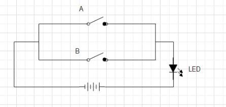
NOTE: WE CAN USE A BULB AS WELL.
Case 1:
Switch A=OPEN, Switch B= OPEN
If both the switches are open, no current flows through the circuit and the LED does not glow.
Case 2:
Switch A=OPEN, Switch B=CLOSED
Due to the parallel connection, even if one of the switches is closed and the other is open, current flows through the circuit. This causes the LED to glow.
Case 3:
Switch A=CLOSED, Switch B= OPEN
Current flows through the circuit, and the LED glows
Case 4:
Switch A=CLOSED, Switch B= CLOSED
If both the switches are closed, high current flows through the circuit, and the LED glows.
| SNO | SWITCH A | SWITCH B | LED |
| CASE 1 | OPEN | OPEN | OFF |
| CASE 2 | OPEN | CLOSED | ON |
| CASE 3 | CLOSED | OPEN | ON |
| CASE 4 | CLOSED | CLOSED | ON |
The Boolean expression for OR Operation is
Y= A + B
Where Y= Output; A= Input 1; B= Input 2
2) AND Operation:
AND Operation is a form of logic multiplication represented by the (.) sign with two or multiple inputs producing a single output. The AND Operation produces HIGH output (1) only if all the inputs to the digital circuit are HIGH (1). If one or both of the inputs are LOW (0), the output of the digital circuit will also be LOW (0).
Let us understand this with an example:
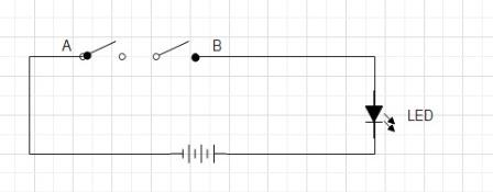
Consider a circuit with two switches connected in series to an LED. The LED would be ON if the current flows through the circuit. For the current to flow, both of the switches must be closed. If either one of the switches is open, the current will not flow.
Case 1:
Switch A=OPEN, Switch B= OPEN
As both the switches are open, the current does not flow through the circuit and the LED does not glow.
Case 2:
Switch A=OPEN, Switch B=CLOSED
If one of the switches is open in a series-connection circuit, the current can’t flow. Hence, the LED does not glow.
Case 3:
Switch A=CLOSED, Switch B= OPEN
If one of the switches is open, the current does not flow through the circuit and the LED does not glow.
Case 4:
Switch A=CLOSED, Switch B= CLOSED
If both the switches are closed, a high current flows through the circuit, and the LED glows.
| SNO | SWITCH A | SWITCH B | LED |
| CASE 1 | OPEN | OPEN | OFF |
| CASE 2 | OPEN | CLOSED | OFF |
| CASE 3 | CLOSED | OPEN | OFF |
| CASE 4 | CLOSED | CLOSED | ON |
The Boolean expression for AND Operation is
Y= A . B
Mostly, the dot (.) is removed
Y= AB
Where Y= Output; A= Input 1; B= Input 2
3) NOT Operation:
NOT is an Operation in the form of logic inversion, known as a complement. There is a single input producing the only output. NOT operation produces a HIGH (1) output for a LOW (0) input and a LOW (0) output for a HIGH (1) input.
It is represented by a bar (ˉ) over the variable.
Let us understand this with an example:
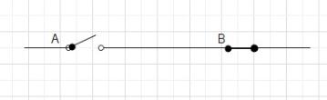
Consider a ganged switch. If one of the switches is open, the other is automatically closed and vice versa.
| SWITCH A | SWITCH B |
| OPEN | CLOSED |
| CLOSED | OPEN |
The Boolean expression for NOT Operation is
Y= Aˉ
Where Y= Output; A= Input
Logic Gates
A logic gate is a digital circuit with a single output whose value depends upon the logical relationship between the input(s) and output. In simple words, The relationship between the input values and the output is based on a certain ‘logic’, hence these circuits are addressed as logic gates.
The logic gates have only one output for a single input or a number of inputs. To understand the operation of a logic gate, a Truth Table is prepared by stating all the combinations of inputs together with the output.
There are 3 types of logic gates–
1) Basic Gates: OR, AND, and NOT Gates.
2) Universal Gates: NAND, and NOR Gates.
3) Derived Gates: XOR Gates, and XNOR Gates.
Also Read: The Fastest Logic Gates Ever
Let’s understand all three logic gates in deep.
1) Basic Gates
There are three types of basic logic gates- OR, AND, and NOT gates. A Basic logic gate behaves the same as the corresponding logic operator.
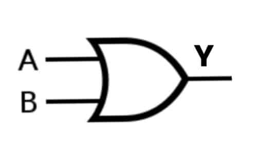
A) OR Gate:
For two or more inputs, the OR gate produces a HIGH (1) output only if one or all the inputs are HIGH (1). It works similarly to the OR Logic operation.
The logical expression for an OR Gate is
Y= A OR B
Case 1: A= 0, B= 0; Y= 0
In this case, both the inputs are LOW (O), so the OR Gate produces LOW (0) output.
Case 2: A= 0, B= 1; Y= 1
In this case, one of the inputs is HIGH (1), so the OR Gate produces the HIGH (1) output.
Case 3: A= 1, B= 0; Y= 1
In this case, one of the inputs is HIGH (1), so the OR Gate produces the HIGH (1) output.
Case 4: A= 1, B= 1; Y= 1
In this case, both the inputs are HIGH (1), hence the OR Gate produces the HIGH (1) output.
OR Gate Truth Table:
| A | B | Y=A OR B |
| 0 | 0 | 0 |
| 0 | 1 | 1 |
| 1 | 0 | 1 |
| 1 | 1 | 1 |
B) AND Gate:
For two or more inputs, AND gate produces a HIGH (1) output only if both the inputs are HIGH (1). It produces a LOW (O) output even if one of the inputs is LOW (0). It works similarly to the AND Logic operation
The logical expression for an AND Gate is
Y= A AND B

Case 1: A= 0, B= 0; Y= 0
In this case, both the inputs are LOW (O), so the AND Gate produces LOW (0) output.
Case 2: A= 0, B= 1; Y= 0
In this case, one of the inputs is LOW (0), hence the AND Gate produces a LOW (0) output.
Case 3: A= 1, B= 0; Y= 0
In this case, one of the inputs is LOW (0), so the AND Gate produces a LOW (0) output.
Case 4: A= 1, B= 1; Y= 1
In this case, both the inputs are HIGH (1), so the AND Gate produces HIGH (1) output.
AND Gate Truth Table:
| A | B | Y=A AND B |
| 0 | 0 | 0 |
| 0 | 1 | 0 |
| 1 | 0 | 0 |
| 1 | 1 | 1 |
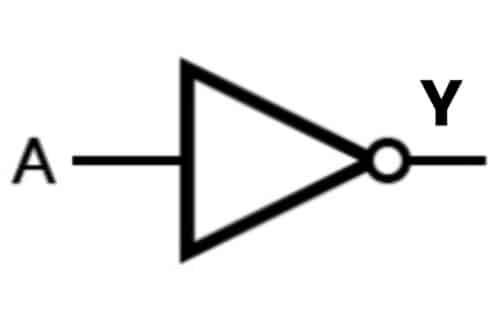
C) NOT Gate:
For a single input, NOT gate produces the output as a complement of the input. NOT gate produces a HIGH (1) output only if the input is LOW (0) and a LOW (0) output if the input is HIGH (1). It works similarly to NOT logic operation.
The logic expression for a NOT Gate is
Y=Aˉ
Case 1: A=0; Y= 1
The input of the NOT gate is LOW (0), so the output becomes HIGH (1).
Case 2: A=1; Y= 0
The input of the NOT gate is HIGH (1), so the output becomes LOW (0).
NOT Gate Truth Table:
| A | Y=Aˉ |
| 0 | 1 |
| 1 | 0 |
Also Read: Researchers Develop Logic Gates Based On Neuristors
2) Universal Logic Gates
The Universal Logic Gates can implement any Boolean expression on its own, this means they don’t require any other gate for implementation. A single Universal Logic Gate is capable of building a logic circuit. There are two types of Universal Logic Gates
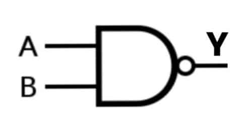
A) NAND Gate:
A NAND Gate is a complement of AND Gate or simply, a combination of NOT Gate and AND Gate. It is called NAND as N stands for NOT, meaning a NOT AND Gate. For two or more inputs, the NAND gate produces a HIGH (1) output only if one of the inputs is LOW (0).
The NAND Gate Boolean Expression is denoted by a complement of AND.
Y= (AB)ˉ
Case 1: A= 0, B= 0; Y= 1
In this case, both the inputs are LOW (O), hence the NAND Gate produces HIGH (1) output.
Case 2: A= 0, B= 1; Y= 1
In this case, one of the inputs is LOW (0), hence the NAND Gate produces a HIGH (1) output.
Case 3: A= 1, B= 0; Y= 1
In this case, one of the inputs is LOW (0), hence the NAND Gate produces a HIGH (1) output.
Case 4: A= 1, B= 1; Y= 0
In this case, both the inputs are HIGH (1), hence the NAND Gate produces LOW (0) output.
NAND Gate Truth Table:
| A | B | Y=A NAND B |
| 0 | 0 | 1 |
| 0 | 1 | 1 |
| 1 | 0 | 1 |
| 1 | 1 | 0 |
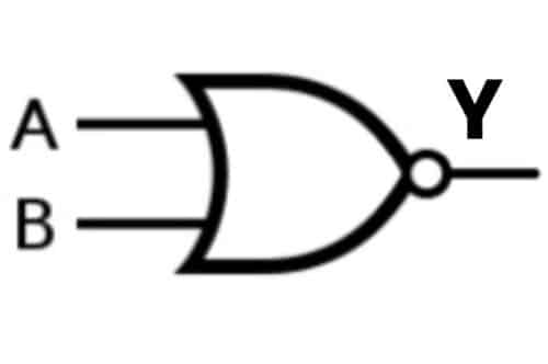
B) NOR Gate:
A NOR Gate is a complement of OR Gate or a combination of NOT Gate and OR Gate. It is called NOR as N stands for NOT, meaning a NOT OR Gate. For two or more inputs, the NOR gate produces a HIGH (1) output; only both inputs are LOW (0).
The NOR Gate Boolean expression is denoted by a complement of OR.
Y= (A+B)ˉ
Case 1: A= 0, B= 0; Y= 1
In this case, both the inputs are LOW (O), so the NOR Gate produces HIGH (1) output.
Case 2: A= 0, B= 1; Y= 0
In this case, one of the inputs is HIGH (1), so the NOR Gate produces the LOW (0) output.
Case 3: A= 1, B= 0; Y= 0
In this case, one of the inputs is HIGH (1), so the NOR Gate produces the LOW (0) output.
Case 4: A= 1, B= 1; Y= 0
In this case, both the inputs are HIGH (1), so the NOR Gate produces the LOW (0) output.
NOR Gate Truth Table:
| A | B | Y=A NOR B |
| 0 | 0 | 1 |
| 0 | 1 | 0 |
| 1 | 0 | 0 |
| 1 | 1 | 0 |
Also Read: Cancer Cells Turned Into Logic Gates
3) Derived Logic Gates:
The derived or special gates are made for specific applications such as half adders, full adders, and subtractors. There are two derived logic gates made from OR and NOR gates.
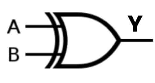
A) Exclusive OR, EX-OR or XOR Gate
Ex-OR gate has two or more inputs but a single output. Ex-OR gate generates a HIGH (1) output if both the inputs are not at the same logic level A≠B.
Case 1: A= 0, B= 0; Y= 0
In this case, both the inputs are LOW (O) at the same logic level. As a result, the Ex-OR Gate produces a LOW (0) output.
Case 2: A= 0, B= 1; Y= 1
In this case, one of the inputs is LOW (0) and the other is HIGH (1). Hence, they are not on the same logic level. As a result, the Ex-OR Gate produces the HIGH (1) output.
Case 3: A= 1, B= 0; Y= 1
In this case, one of the inputs is HIGH (1) and the other is LOW (0). Hence, they are not on the same logic level. As a result, the Ex-OR Gate produces the HIGH (1) output.
Case 4: A= 1, B= 1; Y= 0
In this case, both the inputs are HIGH (1) at the same logic level. As a result, the Ex-OR Gate produces the LOW (0) output.
XOR Gate Truth Table:
| A | B | Y=A XOR B |
| 0 | 0 | 0 |
| 0 | 1 | 1 |
| 1 | 0 | 1 |
| 1 | 1 | 0 |
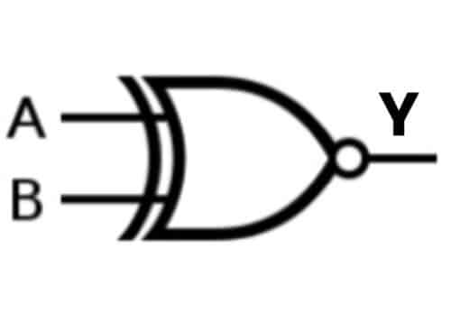
B) Exclusive NOR, EX-NOR, or XNOR Gate
EX-NOR gate has two or more inputs but a single output. EX-NOR gate generates a HIGH (1) output if both the inputs are at the same logic level A=B.
Case 1: A= 0, B= 0; Y= 1
In this case, both the inputs are LOW (O) at the same logic level. As a result, the EX-NOR Gate produces a HIGH (1) output.
Case 2: A= 0, B= 1; Y= 0
In this case, one of the inputs is LOW (0) and the other is HIGH (1). Hence, they are not on the same logic level. As a result, the EX-NOR Gate produces the LOW (0) output.
Case 3: A= 1, B= 0; Y= 0
In this case, one of the inputs is HIGH (1) and the other is LOW (0). Hence, they are not on the same logic level. As a result, The EX-NOR Gate produces the LOW (0) output.
Case 4: A= 1, B= 1; Y= 1
In this case, both the inputs are HIGH (1) at the same logic level. As a result, the EX-NOR Gate produces the HIGH (1) output.
XNOR Gate Truth Table:
| A | B | Y=A XNOR B |
| 0 | 0 | 1 |
| 0 | 1 | 0 |
| 1 | 0 | 0 |
| 1 | 1 | 1 |
We hope you now have a clear idea about all the Logic Gates in Digital Electronics. But if you have any doubts, feel free to ask in the comments below.