


What are Digital Signals and Circuits?
Digital Signals
A Digital Signal is a type of Signal that has two discrete levels, either HIGH (1) or LOW (0). These two levels are usually represented by-
- LOGIC 1 = HIGH = TRUE = ON = YES
- LOGIC = LOW = FALSE = OFF = NO
The concept of the Binary number system is the accurate representation of Digital Signals. Digital Signals work on the principles of Boolean Algebra, binary mathematics developed by George Boolean.

Digital Circuits
Digital Signals operate at high speeds and drive Digital Circuits that contain some basic components such as Diodes, Inductors, Capacitors, Resistors, Batteries, and Logic Gates.
There are many Logic families that follow the principle of Digital Signals. Examples of such Logic families consider 3.5V to 5V voltage as high logic and 0V to 1V as low logic. This means voltage lying anywhere between 3.5V to 5V would be represented by 1 and voltage lying anywhere between 0V to 1V would be represented by 0. The actual value of voltage is not important in digital signals.
Representation for a range of voltages as 1 or 0, makes digital circuit operation simpler than analog or fuzzy circuits. Operating only in two states, either high or low, makes these signals fast, and less susceptible to noise, temperature, and irrespective of the aging components.
As compared to analog systems, Digital circuits follow the concepts of electrical network analysis and have a “memory”.
There are two types of Digital Circuits: Combinational Digital circuits and Sequential Digital Circuits.
- Combinational Digital Circuits are the type of digital circuits in which output depends upon inputs at that present time.
- Sequential Digital Circuits are time-dependent digital circuits in which the outputs depend upon past states as they have memory units.
Digital Circuit Design
Digital Circuits are designed using logic gates, diodes, transistors, inductors, capacitors, and resistors. As Digital Circuits follow Boolean Laws, the logic expressions should be simplified for a small circuit.
Small the digital circuit, the easier for it to be embedded in Integrated Circuits (ICs). This is because the main goal of hardware systems is to reduce IC Packages.
Design Examples
-
Design a Full Adder using two Half Adders
Construction:
The inputs of the first half adder are two single binary digits A and B. The output of the first half adder sum S is fed to the input of the second half adder terminal 1 on K. The sum output of the second half adder is obtained across X.
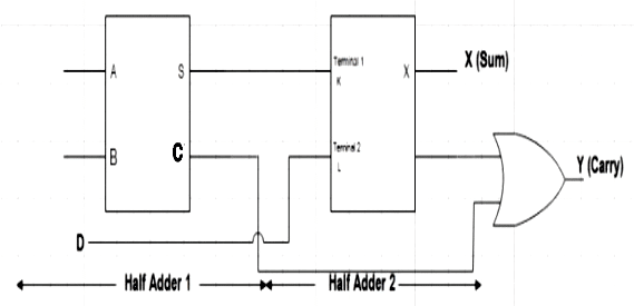
The carry bit D is directly applied across terminal 2 on L of the second half adder. The carry output is obtained across Y of the second half adder.
Operation
The Boolean expression for Output Sum at S of the first half adder,
S= A ⊕ B
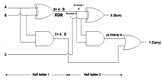
The output across the second half adder for Sum X is a direct XOR operation of S of the first half adder at input terminal 1 and the carry bit at input terminal 2 of the second half adder
X= A ⊕ B ⊕ D
Hence, the expression for the sum of two half adders is the same as the sum of the Full Adder circuit.
The Boolean expression for Output Carry at Y is an OR operation of the output carry of both the first and second-half adders.
Y= (A ⊕ B) D + AB
For this, we have to solve the Boolean expression,
By circuit diagram,
Y= (A’B + AB’) D + AB
Y= A’BD + AB’D + AB
By inserting the Boolean Law of OR,
1+D= D
Y= A’BD+ AB’D + AB (1+D)
Y= A’BD+ AB’D + AB + ABD
Y= BD (A’+A) + AB’D + AB
By using the Boolean Law of OR,
A+A’= 1
Y= BD + AB’D + AB
By inserting the Boolean Law of OR,
1+D= 1
Y= BD + AB’D + AB (1+D)
Y= BD + AB’D + AB + ABD
Y= BD + AD (B’+B) + AB
By using the Boolean Law of OR,
B+B’= 1
Y= BD + AD + AB
The expression for Carry of two half adders is the same as that of a Full Adder.
Hence, by using combinational digital logic, we can design a full adder using two half adders.
-
Design a Full Subtractor using two Half Subtractors
Construction:
The inputs of the first half subtractor are two single binary digits A and B. The output of the first half subtractor difference D is fed to the input of the second half subtractor terminal 1 on K. The difference output of the second half subtractor is obtained across X.
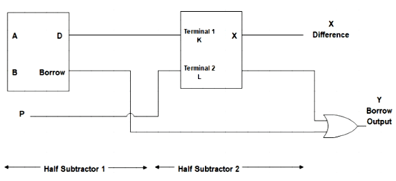
The borrow bit P is directly applied across terminal 2 on L of the second half subtractor. The borrow output is obtained across Y of the second half subtractor.
Operation
The Boolean expression for Output Difference at D of the first half Subtractor is,
D= A ⊕ B

The output across the second half subtractor for Difference X is a direct XOR operation of D of the first half subtractor at input terminal 1 and the borrow bit P at input terminal 2 of the second half subtractor.
X= A ⊕ B ⊕ P
Hence, the expression for the Difference between two half subtractors is the same as the difference of the Full Subtractor circuit.
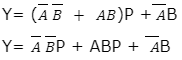
The Boolean expression for Output Borrow at Y is an OR operation of the output borrow of both the first and second-half subtractors.
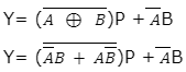
As XNOR is the complement of XOR,
By inserting the Boolean Law of OR,
1+P= 1
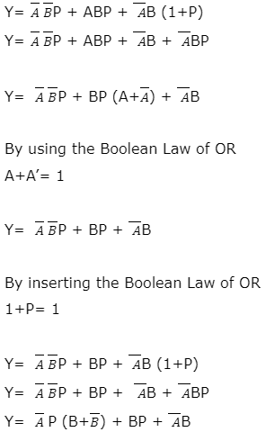
By using the Boolean Law of OR,
B+B’= 1
![]()
The expression for Borrow Output of two half subtractors is same to that of a Full Subtractor.
Hence, by using combinational digital logic, we can design a full subtractor using two half subtractors.
Digital Circuit Design Applications
- Digital Hardware had adapted Digital signals, circuits, and their logic and design concepts since 1938 and continues to work on the same.
- Digital Systems are the key components behind the operations of Computers, Calculators, the Internet, Internet Communication, and Telecommunications.
- Digital circuits and designs are used in
-
- Integrated Circuits (ICs)
- Programmable Logic Devices (PLDs)
- Field-programmable Gate Arrays (FPGAs)
- Digital Computers
- Digital Calculators
- Hardware