


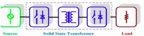
Solid-state transformer (SST) is a collection of high-powered semiconductor components, conventional high-frequency transformers and control circuitry which is used to provide an elevated level of flexible control to power distribution networks. By adding some communication capability, the entire package is often referred to as a smart transformer. SST technology can step up or step-down AC voltage levels just like that of the traditional transformer, but it also offers several significant advantages. They use transistors and diodes and other semiconductor-based devices that, unlike the transistors used in computer chips, are engineered to handle high power levels and very fast switching.
As utilities start to roll out the smart grid, they are focused on gathering information, such as up-to-the-minute measurements of electricity use from smart meters installed at homes and businesses. But as the smart grid progresses, they’ll be adding devices, such as smart solid-state transformers, that will strengthen their control over how power flows through their lines, says Alex Huang, director of a National Research Foundation research centre that’s developing such devices. “If smart meters are the brains of the smart grid,” he says, “devices such as solid-state transformers are the muscle.” These devices could help change the grid from a system in which power flows just one way—from the power station to consumers—to one in which homeowners and businesses commonly produce power as well.

Requirement of SST
- Transformer oil can be harmful when exposed to the environment.
- Core saturation produces harmonics, which results in large inrush currents.
- Unwanted characteristics on the input side, such as voltage dips, are represented in output waveform.
- Harmonics in the output current has an influence on the input. Depending on the transformer connection, the harmonics can propagate to the network or lead to an increase of primary winding losses.
- Relative high losses at the average operation load. Transformers are usually designed with their maximum efficiency at near to full load, while transformers in a distribution environment have an average operation load of 30%.
- All LFTs suffer from non-perfect voltage regulation. The voltage regulation capability of a transformer is inversely proportional to its rating. At distribution level, the transformers are generally small and voltage regulation is not very good.
Advantages of SST over Conventional Transformer
- Voltage Sag compensation
- Outage compensation
- Instantaneous voltage compensation
- Fault isolation
- Power factor correction (& reactive power compensation)
- Harmonic isolation
- DC Output
- Metering or advanced distribution automation
- Environmental benefit
History of SST
The idea of a “solid state transformer” has been discussed since 1970. The initial purpose of solid state transformers is to convert AC to AC for step-up or step down with a function the same as that of a conventional transformer. In1970, W. McMurray form G.E. first introduced a high frequency link AC/AC converter, which became the basis for the solid-state transformer based on direct AC/AC converter.
A high-power AC/AC conversion has been proposed by Moonshik Kangand Enjeti from Texas A&M University. For that topology, the incoming AC wave form is modulated by a power-electronic converter to a high frequency square wave and passed through a small high-frequency transformer. Since 2002, Electrical Power Research Institute (EPRI) has been researching the Intelligent Universal Transformer (IUT).
An intelligent and controllable system can provide multiple transformer functions, such as voltage transformation, voltage regulation, non-standard customer voltages (DC or 400Hz AC), voltage sag correction, power factor control, and distribution system status monitoring to facilitate automation. Researchers at ETH Zurich are working on a MATRIX converter with the codename MAGA Cube. The FREEDM project is investigating an SST based on a single-phase system with modularity in mind from 2010 onwards.

Architectures of SST
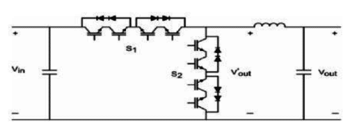
The basic idea of the SST is to achieve the voltage transformation by medium to high frequency isolation, therefore to potentially reduce the volume and weight of it compared with the traditional power transformer. The most commonly used power electronic converter topology is the two-level converters.
The limitation was that even using the highest available power rating 6.5kV IGBTs, a two-level converter-based SST can only interface with 2.4kV AC voltage.
To apply the silicon-based SST to a distribution voltage level 7.2kV/12kV, multi-level converter topology is inevitable.
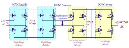
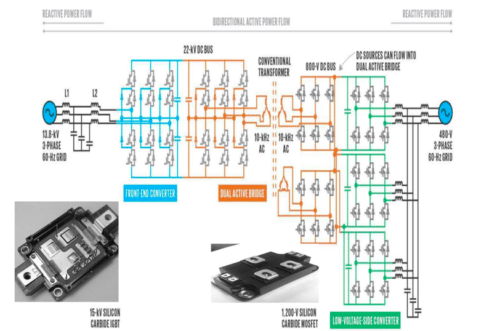
Stage One
- In this stage is a three-phase ac/DC rectifier that regulates a high-voltage DC bus (and ac voltage when for reactive power compensation) is used.
- It produces low distortion grid current.
- DC voltage regulation.
Stage two
It consists of a Dual active bridge (DAB), a high frequency transformer.
DAB converter gives:
- Electrical isolation.
- High reliability.
- Ease of realizing soft-switching control.
Stage three
DC-AC converter is used to convert the DC voltage in desirable voltage.

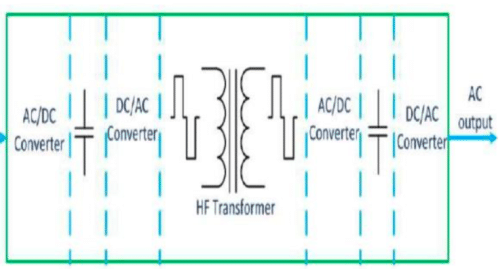
Operation of SST
AC power from the supply is converted into DC power. The AC power can be converted into DC regulated power & gives power factor improvement, voltage control. In DC-DC isolation, it isolates input and output side and power can flow in both directions since DSB is used. High-frequency transformer reduces the size of the overall system and provides reactive power compensation and active power compensation. DC-AC inverter gives both AC and DC output regulation.
Benefits of SST
Size & Weight reduction: One of the most important features of the SST is the voltage sag or swell ride through capability
Voltage Sag mitigation: The voltage sag or swell can be compensated by the rectifier stage and will not affect the load side voltage. The maximum input current determines how much voltage sag the SST can compensate, and the maximum input voltage determines how much a voltage swell the SST can support.
Reactive power compensation: The SST rectifier stage not only converts the input AC to regulated DC voltages, but also has reactive power compensation capabilities. Depending on the reactive power reference in the SST controller, the SST can generate or absorb the rated reactive power to the power grid.
Fault Isolation: The SST protection scheme for the output short circuit is, the SST will stay online but limit the load current.
Applications of SST
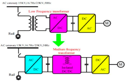
- Traction application
- Smart Grid application
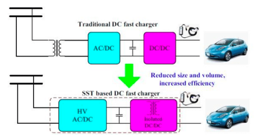
- DC Charge Station
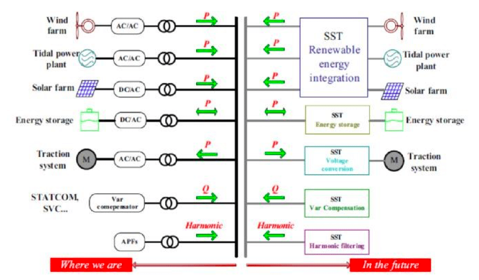
- Wind Power generation

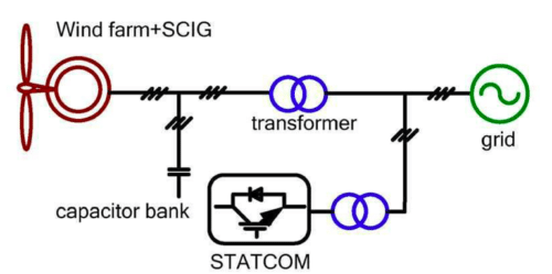
Wind power is an uncontrollable resource, also makes for a challenging integration of large WFs into the grid, particularly in terms of stability and power quality. Integration of SST with wind energy systems effectively replacing the conventional transformer and reactive power compensator to increase the flexibility of wind energy system.
Normally SCIG is used in wind energy system a capacitor bank is generally placed at the terminal of the wind generator for the local reactive power compensation (which is necessary for the operation of the system). The nature of WFs is that their operation is highly dependent on the active and reactive powers transferred to the grid. In any interfacing system there is need for conventional transformer and reactive power compensator. SST-interfaced WF architectures effectively replace the conventional transformer and reactive power compensator.
Implementation Challenges in SST
One of the main disadvantages of the cascaded H-bridge converter is the voltage unbalance that could appear on the DC side of different H-bridges. The unbalance issue becomes worse when the SST operates at no-load or light-load condition, because a small power difference is a significant percentage of the real power and will result in a large voltage unbalance. Smart solid-state transformers are still in the development stage and likely are a few years away from being ready for market—researchers are still working on their efficiency and cost, for example. Taking advantage of their DC capability will require developing new construction standards for homes and businesses.
Mark Wyatt, the vice president of smart-grid and energy systems at Duke Energy, cautions that solid-state transformers will need to be supplemented with other devices for controlling power on the grid, and they may not prove cost-effective in many areas. “It’s not one size fits all,” he says. Yet in the long term, Huang says, smart transformers and other smart solid-state devices could enable an unprecedented amount of two-way power flow. “It could be revolutionary to how we construct the grid,” he says.
Future Research Areas
This set of shelves at the FREEDM Systems Center houses part of TIPS, a three-phase solid-state transformer. The conventional transformer component of TIPS [gray boxes at bottom] can be small thanks to power electronics that convert the electricity to high frequency. In the near term, SSTs could be a boon for disaster-recovery efforts in places with damaged electrical infrastructure and for settings such as naval vessels, where volume and weight are at a premium. Further in the future, they could redefine the electrical grid, creating distribution systems capable of accommodating a great influx of renewable and stored energy, dramatically improving stability and energy efficiency in the process. Highly variable, two-way flow of electricity between a microgrid and the main grid.
Conclusion
The technological review of concepts and developments in field of Solid State Transformer has been shown. Also, various configurations used and implemented so far have been briefly reviewed.
Finally, it is concluded that the conventional transformer which is used widely in industrial applications so far having disadvantages like saturation of core for non-linear load, poor voltage regulation, bulkiness.
Majority of these problems can be reduced or eliminated by solid state power electronic based intelligent transformer. Also, it has the capability to work as energy router for smart grid energy internet.
The field of application of power electronic based solid-state transformer is not limited to only the distribution level but research work suggests that these intelligent solid-state transformers have the capacity to replace the conventional power transformer too soon.
The idea of a “solid state transformer” has been discussed since 1970. The initial purpose of solid state transformers is to convert AC to AC for step-up or step down with a function the same as that of a conventional transformer. In1970, W. McMurray form G.E. first introduced a high-frequency link AC/AC converter, which became the basis for the solid state transformer based on direct AC/AC converter.
Rohit P R, Rahul P R are students of Electrical & Electronics Engineering at CMR Institute of Technology, currently in their 8th semester. Their topics of interest are IoT, Power Systems, Renewable Energy and other emerging technologies in the field of Electrical & Electronics. They are avid quizzers, IEEE student members and have participated in various workshops.
this solid converter must be the dream Electronics producers and Envier protection.