


A transformer is a static device that transfers electric power between two alternating current circuits with no change in frequency. The Voltage of the circuit can be reduced or increased in accordance with the current relationship. This is known as stepping up (increasing) the voltage and stepping it down (decreasing).

The transformer is a passive device that works on the principles of electromagnetic induction used at the input to step up the voltage and step down the output voltage at the outer terminal.

Table of Contents
Transformer Construction
There are three components of a Transformer:
- Iron Core
- Primary Winding
- Secondary Winding
Core
The core of the transformer is rectangular in shape and laminated. During the transformer construction, it has to be designed in such a way that there are fewer core losses during the operation of the Transformer. Core losses and iron losses are a combination of all the losses that happen inside the core.
The core lets an alternating flux drive through it. This might cause energy loss in the core due to hysteresis loss. So, you should choose a high-quality Silicon Steel with low hysteresis loss to construct the core of a Transformer. This steel is termed the Soft Steel Core of the Transformer.
The alternating flux produces certain currents known as Eddy currents. These currents use electrical energy and cause certain losses, known by the name of eddy current losses of the Transformer. The core must be manufactured as a group of laminations. These successive laminations are electrically insulated to reduce eddy currents. The insulation layer is made up of Varnish, which offers high resistance to eddy currents.
Windings
There are two windings on the transformer i.e. Primary Winding and Secondary Winding. The Primary Winding is connected to the input terminal and is responsible for generating a self-induced EMF. The Secondary Winding is connected to the output load. These windings are placed on the core and are electrically insulated from each other and the core for proper functioning and reduction in losses.
These coils have different numbers of turns compared to each other. The Primary Winding of the Transformer has N1 turns. Similarly, the Secondary Winding of the Transformer has N2 turns. Depending upon the operation of the transformer, N1< N2, N1> N2, and N1= N2.
Types of Transformer Construction
There are two designs of Transformers depending upon the placement of the core and the coils during the transformer construction.
Core-type Construction
The Primary Winding is bound on one end of the iron core, and the Secondary Winding is placed on the other end. Each of the coils is divided into equal parts and placed on the two ends of the iron core. Both the windings enclose the whole core.
Although Primary and Secondary Windings are electrically insulated from each other, both of them are connected in series in core-type construction.
This increases the average length of the core and provides a good magnetic coupling between both of the windings. The magnetic flux follows a continuous path and generates an EMF.
The core-type transformer construction is suitable for high-voltage transformers. They are common among both types of constructions and are easy to repair due to their easy arrangement, in case of any damage.
Shell-type Construction
The shell-type construction allows the core to surrounding Primary and Secondary Windings. There are three faces of the iron core- left, central, and right face. The primary and secondary coils are bound to the central face of the iron core. The core encloses both the windings and the average length of the core is less.
Although electrically insulated from each other, the primary and secondary coils generate different voltages V1 and V2. This distributes magnetic flux into two parts. The shell-type construction of the Transformer is suitable for low-voltage transformers but is difficult to repair due to their complicated arrangement, in case of any damage.
Working Principle of a Transformer
A transformer is made from a core that has common input and output sides. Two inductive windings are embedded in this core which is electrically insulated from each other. The input coil in which electrical voltage is fed is known as Primary Winding. The output coil from which the electrical voltage is drawn is called the Secondary Winding.
You can check the detailed explanation video of how a transformer works.
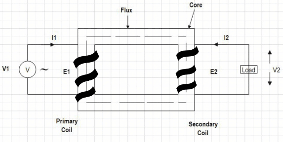
When an input alternating voltage V1 is applied across the primary coil of the transformer, it generates an alternating current I1. An alternating electromotive force emf e1 is produced in the core.
According to Faraday’s law of electromagnetic induction,
An electromotive force emf e1 runs through the primary coil.
Where,
- EMF is a first-order time derivative of Electromagnetic Flux.
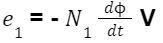
- e1= Electromotive Force
- N1= Number of Turns in a primary coil
The electromagnetic flux emf e1 is indirectly equal and opposite to the input alternating voltage V1.
If we assume that the leakage flux is negligible and there are no losses in the transformer.
Due to Faraday’s law of electromagnetic induction, an Electromotive Force emf e2 is produced in the secondary coil.
An electromotive force emf e2 runs through the secondary coil.
Where,
- EMF is a first-order time derivative of Electromagnetic Flux.
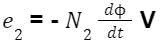
- e2= Electromotive Force
- N2= Number of Turns in a secondary coil
As per Faraday’s laws, the emf e1 is a self-induced electromotive force, and emf e2 is a mutually-induced electromotive force.
The energy transfer takes place through primary to secondary winding with mutual induction. The secondary coil is closed through a load as the current I2. flows through the circuit.
Based on the number of turns in the primary and secondary windings, we can design a step-up or step-down transformer.
Step-up and Step-Down Transformers
Step-up Transformer
If
N1 < N2
e1 < e2
A Step-up Transformer is defined as a device that receives an electrical alternating voltage and converts it into a higher voltage. It is the transformer that has more turns in the secondary winding compared to the primary coil. Used in the input terminal of the transmission line.
Step-down Transformer
If
N1 > N2
e1 > e2
A Step-down Transformer is defined as a device that receives an electrical alternating voltage and converts it into a lower voltage. It is the transformer that has more turns in the primary winding compared to the secondary coil. Used in the output terminal of the transmission line.
Isolation Transformer
N1 = N2
This is known as the Isolation Transformer in which the number of turns is equal in the primary and secondary windings. This means that the induced voltages and current values for primary and secondary coils are equal.
This kind of transformer is used to provide Galvanic isolation, reduce noise, and offer protection against electric shocks between conductors and the ground.
Designing a Transformer
EMF Equation of a Transformer
The EMF equation of the Transformer is important to design a step-up or step-down configuration.
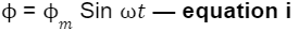
An alternating voltage that is sinusoidal in nature is applied as an input across the primary winding. According to the operation of the transformer, the alternating voltage produces a flux in the iron core. This alternating flux varies sinusoidally across the transformer.
The equation of alternating flux in the iron core of the transformer
According to Faraday’s laws of electromagnetic induction, the EMF e1 is self-induced and EMF e2 is mutually-induced.
The self-induced EMF e1 of the primary winding is given by
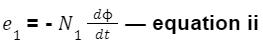
By putting the values of equation 1 in equation 2
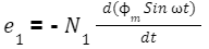
Differentiating with respect to t,
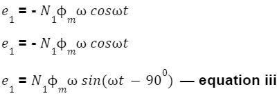
By comparing equations i and iii, we can conclude the self-induced EMF e1 lags behind the electric flux by 900.
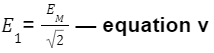
The standard equation becomes-
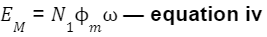
The root mean square RMS value of EMF in Primary Winding is given by-
By equation iv,
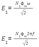
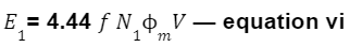
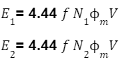
The self-induced EMF e1 in Primary Winding is given by:
Similarly, the mutually-induced EMF e2 in Secondary Winding is given by:
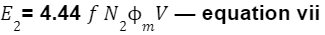
Where, f is the supply frequency, and m is the maximum flux.
These equations (Equations vi and vii) are known as EMF equations of the Transformer.
Flux Density (BM)
The Maximum Flux Density BM in the magnetic core is expressed in Tesla with the inverse relationship to the area of cross-section (A).

The coil with a more number of turns will have a higher voltage winding, and the coil with a less number of turns will have a lesser voltage winding.
Transformer Ratio (K)
The Transformer Ratio (K) is a crucial factor during transformer construction in designing a step-up, and step-down transformer.
Considering the EMF equations of a Transformer by (Equation vi, and vii),
Dividing equation vii by equation vi,
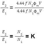
This Ratio is known as the Transformer Ratio (K).
If we consider primary and secondary voltage drop to be 0,
V1= E1 — equation viii
V2= E2 — equation ix
Dividing equation ix by equation viii
K = E2/E1 = V2/V1
If we consider the transformer losses to be 0,
V1I1= V2I2 — equation x
Rearranging equation x,
K = I1/I2 = V2/V1
The Transformer Ratio Formula becomes
K = N2/N1 = E2/E1 = V2/V1 = I1/I2
For Designing
Step-up Transformers,
N1 < N2
K > 1
Step-down Transformers,
N1 > N2
K < 1
Isolation Transformers,
N1 = N2
K = 1
Ideal and Practical Transformers
Ideal Transformer
An ideal Transformer is a theoretical transformer in which there are no losses. The transformer which has been described above is an ideal transformer in which no core losses occur on either side of the transmission line.
But in real-time systems, an ideal transformer does not exist. Instead, a practical transformer with losses is found in use.
Practical Transformer
In a Practical Transformer, the Primary, and Secondary Windings are not ideal as they have a small-value resistance. It is responsible to cause some power loss in the windings, this loss is known as Copper Loss.
The alternating flux produces certain currents inside the transformer, these are known as eddy currents. Eddy current loss and hysteresis loss combine to make Core Loss. Moreover, it has been observed that there is a leakage in electric flux near the windings.
Ideal Transformer vs Practical Transformer
The Core, and Copper Losses of the Transformer with any other leakages as such make up a Practical Transformer. The voltage regulation of the Practical Transformer is never 0%, and efficiency ranges between 93-97%.
While in the Ideal Transformer, there is no resistance of Primary, and Secondary Windings. The absence of resistance causes no voltage drop or power loss. There is no leakage of electric flux near the windings in an ideal transformer.
Furthermore, there are no eddy currents produced by the windings and no hysteresis losses. Hence, an Ideal Transformer has no Copper, and Core Losses with no Electric Flux leakage. The voltage regulation of the Ideal Transformer is 0%, and efficiency is 100%. But this is impossible to construct and exists in hypothetical experiments.
Uses of Transformers
Input and Output of a transmission line
In a traditional power system, you can notice that the input voltage is typically 11kV/22 kV. It is passed through the step-up transformer to generate a voltage level of 220kV/400 kV.

High voltage to run a circuit or transfer between two systems increases efficiency and reduces line losses. When the circuit performs its operation, you can find that the output of the traditional power system uses a step-down transformer. At the end of the transmission line, the running voltage is again reduced to 11 kV/22 kV.
Power Distribution
At the time of Power Distribution, transformers convert a line voltage of 400 V to a phase voltage of 230 V.
Power Loss Decrease
The transformer transmits the same amount of Power but increases the voltage level. This decreases the current flowing through the circuit. The decreased current flow causes the power losses Loss=I2R to decrease in the transmission line.
If you have any doubts or questions, please feel free to ask in the comment section below.
