


Time-lapse photography is a technique that captures a series of images at set intervals over an extended period, which are then compiled into a video to show changes that occur slowly over time—like plant growth, weather patterns, or construction progress—in a condensed format.
A time-lapse camera is a specialized device that automates this process, making it an invaluable tool for various applications. These cameras are designed to be compact, energy-efficient, and capable of operating autonomously for long durations, often in remote or challenging environments.
Industrial Applications of Time-Lapse Cameras
In industries, time-lapse cameras serve multiple purposes:
- Construction and Infrastructure: They monitor project progress, capturing daily or hourly updates to create visual timelines for stakeholders or to analyze workflow efficiency.
- Agriculture: Farmers use time-lapse to study plant growth cycles, track seasonal changes, or monitor the effects of environmental conditions on crops.
- Environmental Research: By rivers, seas, or forests, these cameras record natural phenomena like tidal changes, erosion, or wildlife behaviour over months or years.
- Laboratories: In scientific settings, time-lapse cameras document experiments, such as chemical reactions or biological processes, where changes occur gradually.
- Manufacturing: They help in observing production lines, identifying bottlenecks, or documenting equipment wear over time.
The need for compact, versatile, and wireless time-lapse cameras has grown, especially for deployments in hard-to-reach areas where continuous monitoring without human intervention is critical.
Here we will design two versions to cater to diverse needs. The Wi-Fi Mode operates in Access Point (AP) mode, creating its own WiFi network to stream live video and allow users to set intervals (e.g., 2 seconds to 1 hour) via a web interface, making it ideal for remote monitoring like plant growth in gardens, tidal changes by rivers, or lab experiments, where wireless access and real-time configuration are essential.
Conversely, the SD Card Mode is built for standalone operation in areas without WiFi, such as forests or by the sea, capturing images at a predefined interval to an SD card.
As we need the camera to be easily deployed anywhere, even in a small space so we need a small board. Here we use the IndusBoard Coin in design because it’s small and 3cm with inbuild Wi-Fi and has enough 30+gpios that help us to connect with both the camera and the SD card as well.

Bill of Materials (BOM)
| Component | Quantity | Description |
| IndusBoard Coin V2 | 1 | 3cm Dev board with WiFI development board |
| OV2640 Camera Module | 1 | Camera module compatible with ESP32 |
| SD Card Reader Module | 1 | SPI-based SD card reader |
| MicroSD Card (8GB) | 1 | Storage for images (FAT32 formatted) |
| Push Button | 1 | For starting/stopping time-lapse (SD mode) |
| Jumper Wires | 10 | For connections |
| Power Supply (5V USB) | 1 | Power source (or battery for portability) |
DIY Time-lapse Camera – Connection
Here, the camera is connected with pins as in a circuit diagram and defined in code. The pins can be changed as per need by defining the pins connected and used, and configuring the same in code.
The OV2640 camera module connects to the IndusBoard Coin V2 with the following pin definitions and purposes:
- PWDN_GPIO_NUM -1: Power Down pin, not connected (camera always on).
- RESET_GPIO_NUM 2 (pin 2): Resets the camera, connected to GPIO2 for hardware reset.
- XCLK_GPIO_NUM 44 (pin 42): External Clock, provides the 20 MHz clock signal to the camera.
- SIOD_GPIO_NUM 8 (pin 9): I2C SDA (SCCB), for data communication with the camera.
- SIOC_GPIO_NUM 9 (pin 10): I2C SCL (SCCB), for clock signal in communication.
- Y9_GPIO_NUM 6 (pin 6) to Y2_GPIO_NUM 7 (pin 7): 8-bit data lines (Y9 to Y2) for pixel data transfer, connected to GPIO6, GPIO41, GPIO5, GPIO42, GPIO4, GPIO10, GPIO3, and GPIO7.
- VSYNC_GPIO_NUM 21 (pin 21): Vertical Sync, signals the start of a new frame.
- HREF_GPIO_NUM 1 (pin 37): Horizontal Reference, signals the start of a new line.
- PCLK_GPIO_NUM 39 (pin 39): Pixel Clock, synchronizes data transfer on Y9-Y2 lines.
These pins can be redefined in the code and rewired if needed. The camera also connects to 3V (pin 1) and GND (pin 3) for power.
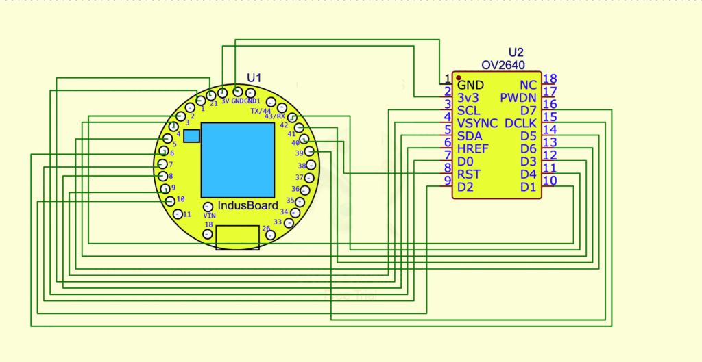
The SD card reader module is connected to the IndusBoard Coin V2 using the default SPI pins, as specified in the circuit diagram. These pins can be redefined in the code if different pins are preferred, as long as they are free and compatible with SPI communication. Below are the details of the connections and the purpose of each pin.

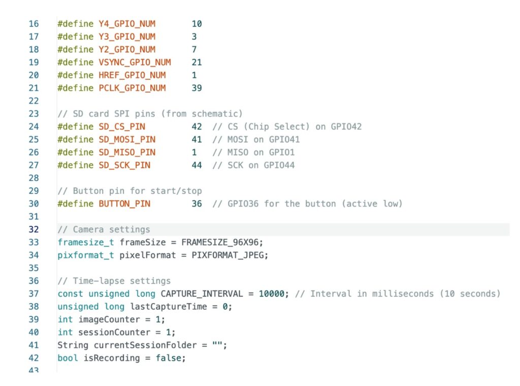
For the SD card-based version, the SD card pins are defined, and the interval time needs to be configured in code.
Testing
Wi-Fi Mode Testing:
- Setup: Connected the OV2640 camera to the IndusBoard Coin V2 as per the pin assignments. Powered the board via USB or using a 3.7 or 3.3V battery using the 3V and GND pins on the coin.
- Procedure:
- Uploaded the WiFi mode code (from the second response).
- Connected to the “IndusCam-AP” network (password: “12345678”) from a laptop.
- Accessed the web interface via the IP address (e.g., 192.168.4.1).
- You will get the webUI where you can find the buttons to set the interval record and stop.
- Set the interval to 10 seconds, started the time-lapse, and monitored the live stream.
- Stopped the session after 1 minute (6 frames) and downloaded the WebM video.
SD Card Mode Testing:
- Setup: Connected the OV2640 camera, SD card module, and button to the IndusBoard. Inserted an 8GB microSD card (FAT32 formatted). Powered via USB.
- Procedure:
- Uploaded the SD card mode code (from the last response).
- Pressed the button to start the time-lapse (interval set to 10 seconds).
- Let it run for 1 minute, then press the button to stop.
- Removed the SD card, inserted it into a computer, and checked the /timelapse_001/ folder.
- Used FFmpeg to create a video: ffmpeg -framerate 1 -i img_%04d.jpg -c:v libx264 -r 30 -pix_fmt yuv420p timelapse.mp4.
