


Balanced charging of each cell in a battery pack is critical to meeting system requirements and maximising lifespan, while continuous monitoring of temperature, current, and charge level ensures safe, efficient operation. Although conventional chargers and BMS modules provide basic balancing and protection, they often fall short of delivering real-time wireless monitoring for remote battery status and health tracking.
POC Video Tutorial
This IoT-based balanced cell charger and monitoring system is a compact, real-time battery management solution for multi-cell Li-ion/LiPo packs ranging from 1S to 4S. It accurately monitors individual cell voltages, per-cell temperature, pack current and power, state of charge (SoC), and overall pack health. Support for 1S to 4S packs means the system can handle battery packs with 1 to 4 cells connected in series, covering an approximate voltage range of 3.7V to 14.8V for Li-ion/LiPo cells.
| Bill Of Materials | ||
| Name | Designator | Quantity |
| 10k | R1-R5, R7, R9, R12 | 8 |
| 47k | R6, R8, R10, R11 | 4 |
| 10k NTC thermistor | S1, S2, S3, S4 | 4 |
| INA219 current sensor | S5 | 1 |
| IndusBoard COIN V2 | U1 | 1 |
| Multi-cell 2S/3S/4S Type-C | U2 | 1 |
| 4-cell 18650 battery holder | U3 | 1 |
All collected data is presented on a clear, responsive web dashboard featuring live per-cell line graphs, colour-coded status cards (green for full, red for critically low), and intuitive battery level indicators. The system also supports dynamic configuration for 1S to 4S packs, different battery chemistries, and capacities, while operating seamlessly in both Station mode (connected to home Wi-Fi) and Access Point (AP) mode.
In this design, an additional voltage sensor and current sensor are placed at the battery’s main terminal to measure overall pack voltage, charge level, load current during operation, and corresponding power consumption. Separate voltage sensors are also used for up to four cells, along with an NTC thermistor for each cell, enabling individual monitoring of cell voltages, charging behaviour, and cell temperature.
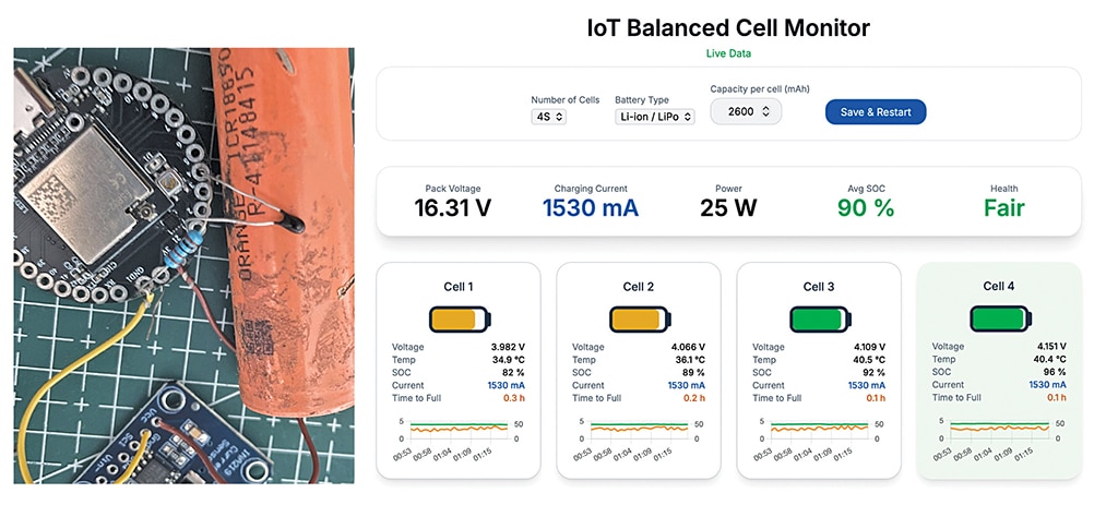
Fig. 1 shows the author’s prototype under testing. The components required to build this system are listed in the Bill of Materials table.
Circuit and working
Fig. 2 shows the circuit diagram of the battery pack balanced-cell charge-monitoring system. It is built around the IndusBoard COIN V2, along with an NTC thermistor network, a multi-cell (2S/3S/4S) Type-C charging module, a 4-cell 18650 battery holder, the INA219 current sensor, and a few passive components. The design integrates voltage sensing, temperature monitoring, and current measurement into a compact microcontroller-based system.

In this circuit, the voltage of each cell is measured individually to estimate its SoC. A resistor divider network is used to scale down the cell voltage to a level suitable for the microcontroller’s analogue input. Although this is a concept design, higher accuracy can be achieved by replacing the divider with a dedicated SoC measurement unit based on Coulomb counting. However, for simplicity and cost-effectiveness, the resistor divider method is used here.
Temperature monitoring is implemented using 10k NTC thermistors, with one thermistor attached to each cell with thermal paste or adhesive to ensure proper thermal contact. These sensors interface with the microcontroller for real-time temperature tracking. The INA219 sensor is connected to the battery pack’s main terminal to measure overall current during charging and discharging, enabling efficient performance monitoring.
Software
The software is developed using the Arduino framework for the IndusBoard COIN V2 (ESP32-S2), utilising libraries such as WiFi.h, ESPAsyncWebServer.h, Wire.h, and the Adafruit INA219 library. The device supports both Station (STA) mode for connecting to an existing Wi-Fi network and AP mode to create its own hotspot.
An asynchronous web server hosts a real-time dashboard built with HTML, CSS, and JavaScript, allowing live monitoring without page refresh. The firmware reads cell voltages via ADC pins and current via the INA219 over I²C, processes the data, and updates the dashboard continuously for effective battery monitoring.
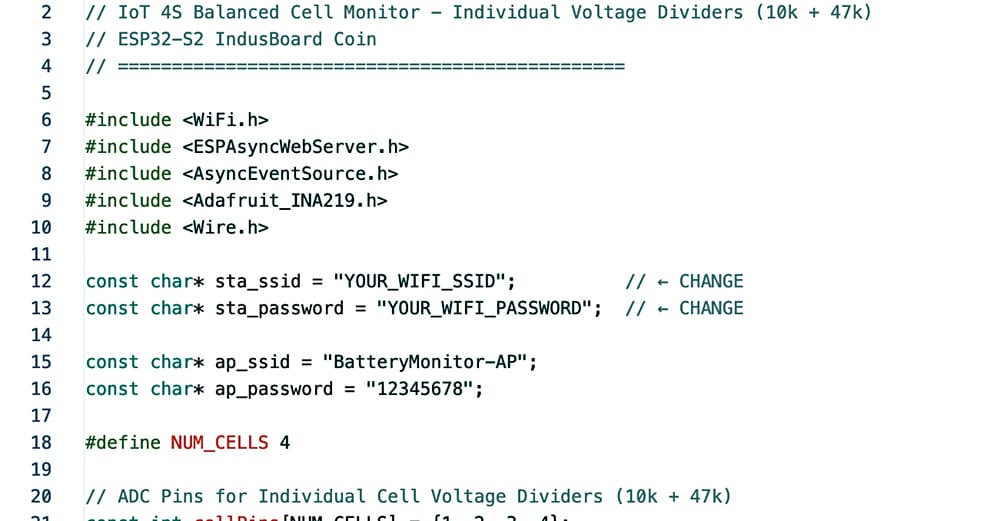
In the firmware section, the first step is to configure the Wi-Fi credentials (SSID and password) to enable network connectivity. The default number of cells in the battery pack is then defined in the code, allowing flexibility for 2S, 3S, or 4S configurations. After this, an embedded web interface is developed using HTML, CSS, and JavaScript to create a real-time dashboard for monitoring battery parameters.
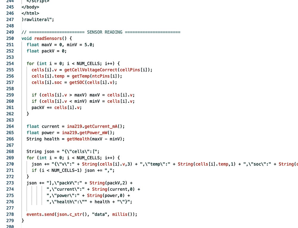
Next, sensor-handling functions are implemented to read data from the ADC pins and the INA219 current sensor. These functions calculate individual cell voltages using resistor divider values and derive temperature readings from the NTC thermistors. The collected data is processed to estimate key parameters such as voltage, current, temperature, and approximate SoC for each cell.
The processed data is then transmitted to the web dashboard, where it is displayed in a user-friendly format. The dashboard shows overall battery pack voltage, current, and power, indicating whether the battery is charging or discharging. It also provides individual cell details, including voltage, temperature, SoC, and basic health status, enabling effective monitoring and diagnostics.
Fig. 3 shows the code snippet for Wi-Fi configuration, while Fig. 4 shows the code snippet that processes sensor data and calculates charge, current, and temperature from the readings obtained via the I/O pins of the IndusBoard COIN V2.
Construction and testing
First, upload the source code to the IndusBoard COIN V2, as shown in the author’s prototype (Fig. 1). Power on the device, and it will attempt to connect to the configured Wi-Fi network. Once connected, the assigned IP address will be displayed on the serial monitor for dashboard access.
If the Wi-Fi connection is not established, the device automatically switches to AP mode. In this mode, the board’s Wi-Fi network can be accessed directly using the predefined SSID and password. This ensures easy access to the system even without an external router.
After assembling the circuit as per the diagram, connect the battery cells and attach the NTC thermistors to each cell using thermal paste. Also connect the current sensor to the main terminal of the battery pack. Once everything is set, open a web browser on a mobile device or laptop connected to the same network, enter the IP address, and access the dashboard for real-time monitoring.
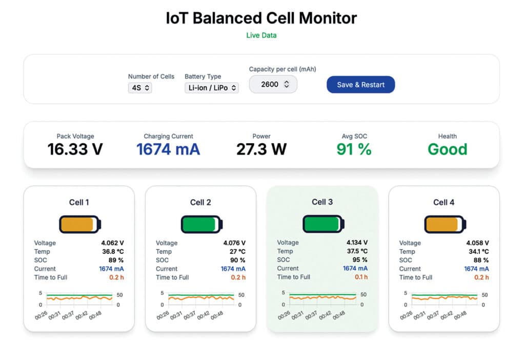
The dashboard allows configuration of the number of cells (1S to 4S or more), battery type (Li-ion, NiMH, etc), and cell capacity. It displays key parameters such as total battery voltage, current, power, individual cell temperature, and estimated SoC. Fig. 5 shows the IoT dashboard displaying real-time battery pack data.
Ashwini Kumar Sinha, an IoT and AI enthusiast, is Tech Journalist at EFY.