
In the previous article in this series, ‘Open Source Model Rocket: Design And Simulation (Part 1),’ published in June issue, the model rocket was designed using simulation software and its performance was evaluated through virtual flight tests. Building on that work, Part 2 covers the assembly process, circuit connections, flight computer programming, and testing, culminating in the construction of a physical model rocket based on the earlier design.
Part 2 focuses on the rocket’s electronics and stabilisation system. Sensors measure altitude and detect changes in motion, enabling the controller to actively stabilise the rocket by adjusting the aerodynamic fins during flight. The controller can also be programmed to modify the rocket’s flight path according to a predefined trajectory.
POC Video Tutorial
To ensure stable flight, proportional-integral-derivative (PID) tuning is performed for self-balancing and fin stabilisation. This enables the rocket to compensate for wind, turbulence and other external disturbances while maintaining its intended flight trajectory.
While full-scale rockets rely on dedicated flight computers, this model uses a simple microcontroller and straightforward programming to implement the same core functions. During testing, the system transmits real-time flight data and fin-control commands over Wi-Fi within its operating range. For longer-range operation, a dedicated telemetry module can be added to transmit flight data to a ground station or another receiving device.
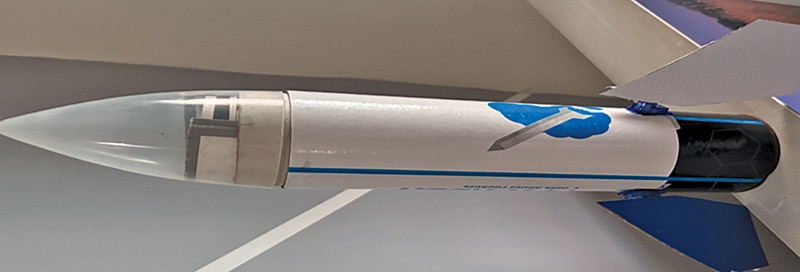
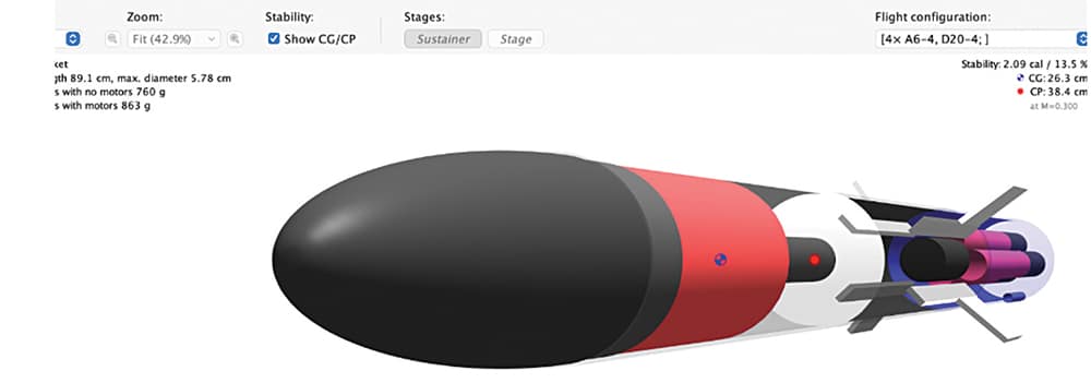
Fig. 1 shows the assembled open source model rocket with a detachable nose cone, while Fig. 2 shows the author’s model rocket prototype alongside its OpenRocket simulator design.
To build this system, the required components are listed in Table 1 and Table 2. Table 1 presents the bill of materials for the rocket body, while Table 2 lists the bill of materials for the rocket’s electronics.
| Table 1 Bill of Materials For The Rocket Body | |||
| Category | Component | Specification | Recommended Range/Notes |
| Structure | Body tube | 3D-printed tube or a standard commercially available body tube | Diameter and length should match the selected rocket design and corresponding part number. |
| Structure | Nose cone | 3D-printed (PLA/PETG) or a standard commercially available nose cone | Select the dimensions and part number based on the finalised design and simulation results. |
| Structure | Fins | Three aerodynamic fins | Use three identical fins designed according to the simulation model. |
| Structure | Model rocket engine | Estes C6-5 (ES1507) or equivalent model rocket engine | Select the engine according to the rocket design, weight, and thrust requirements. |
| Structure | Launch lug | Small guide tube | Inner diameter: 5mm-8mm; ensure it is aligned straight with the rocket body. |
| Structure | Nose weight | Steel or lead weight | Adjust the weight to shift the centre of gravity (CG) forward for stable flight. |
| Table 2 Bill of Materials For The Rocket Electronics | |||
| Category | Component | Specification | Quantity |
| Flight computer | IndusBoard coin | IndusBoard coin programmed with the flight computer and stabilisation firmware | 1 |
| Fin control | Servo motor | Micro gear servo motor for active fin control | 3 |
| Power | Li-po battery (3.7V) | Lithium-polymer battery for powering the rocket electronics | 1 |
| Communication | Telemetry module | Wireless telemetry module for transmitting flight data to a ground station | 1 |
| Video | FPV camera | First-person view (FPV) camera for live launch and in-flight video transmission | 1 |
| Altitude sensing | BME280 | Sensor to measure atmospheric pressure, altitude, and ambient temperature | 1 |
| Motion sensing | MPU6050 | 3-axis gyroscope and 3-axis accelerometer for orientation and acceleration measurement | 1 |
Circuit and working
The complete flight control and stabilisation circuit is shown in Fig. 3. It is built around the IndusBoard Coin, which acts as the flight controller. Three micro servo motors provide active fin control, while an MPU6050 IMU supplies gyroscopic and acceleration data. A BME280 sensor measures atmospheric pressure, altitude, and ambient temperature. Both sensors communicate with the IndusBoard Coin through the I²C interface, and the servo motors are connected to PWM-capable GPIO pins. A regulated 5V supply powers the servos, with all modules sharing a common ground.
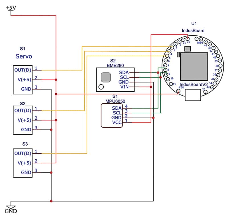
In this prototype, the IndusBoard Coin is used for testing and simulation in place of a dedicated flight controller. Its built-in accelerometer and magnetometer provide orientation, acceleration, and heading information, while the external MPU6050 enhances attitude estimation with precise gyroscopic measurements. Together, these sensors enable the controller to detect deviations caused by wind, turbulence, or other external disturbances and adjust the servo-controlled fins to maintain a stable flight path. The BME280 provides altitude and environmental data, which are also transmitted as part of the rocket’s telemetry.
Assemble the electronics according to the circuit diagram shown in Fig. 3, then securely mount the controller board, sensors, and battery inside the rocket body. Ensure that the battery and electronics are firmly fastened and adequately protected from the heat and exhaust of the rocket motor. Finally, maintain the centre of gravity (CG) and centre of pressure (CP) as determined during the design and simulation phase described in the previous article to ensure stable flight.
Programming the flight controller
Prepare the firmware for the flight controller. The program uses PID control along with sensor calibration to actively stabilise the rocket during flight. The firmware continuously reads data from the onboard sensors, processes orientation and altitude information, and adjusts the servo-controlled fins using a PID algorithm to maintain a stable flight trajectory.
The firmware also configures the IndusBoard Coin as a Wi-Fi access point (AP) to transmit real-time telemetry, including altitude, orientation, acceleration, pressure, temperature, and servo positions. The same telemetry data is simultaneously transmitted through the UART interface (TX: GPIO 43 and RX: GPIO 44), allowing an external radio telemetry module to be connected for long-range communication with a ground station during flight.
In addition, the firmware logs the flight parameters throughout the flight. After recovery using a parachute, the recorded data can be analysed to evaluate the rocket’s performance and further optimise the design, PID parameters, and flight characteristics for subsequent launches.
EFY note. Proper PID tuning ensures stable flight by compensating for wind, turbulence, and other disturbances.
Software/Coding
The Arduino IDE is used to develop, compile, and upload the flight controller firmware. Before compiling the code, install the required BME280 and MPU6050 libraries in the Arduino IDE. After completing the firmware, select the correct board and COM port in the Arduino IDE, then compile and upload the firmware to the IndusBoard Coin. Ensure that all sensors and servo motors are functioning correctly before proceeding with flight testing.
Assembly
Begin by assembling the rocket body, including the body tube, nose cone, fins, launch lug, and other mechanical components.
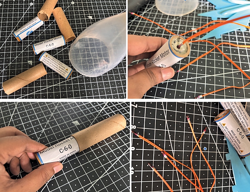
Next, prepare the rocket motor and igniter. Carefully install the motor mount at the bottom of the rocket body tube and ensure that it is firmly secured. Insert the Estes C6-5 model rocket engine, or the engine selected for the design, into the motor mount. Then insert the igniter into the nozzle until its tip makes contact with the propellant inside the motor. Secure the igniter in place using the supplied plastic igniter plug.
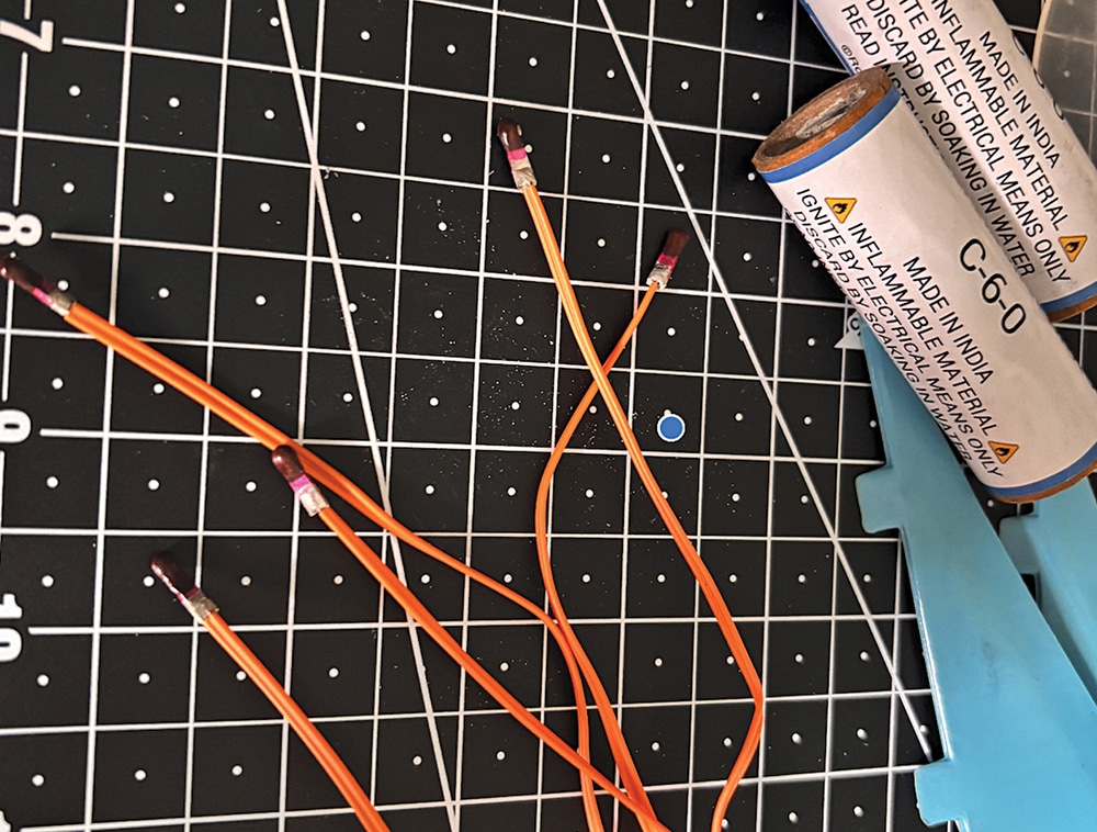
Once the motor and igniter have been prepared, slide the motor fully into the motor mount and lock it securely. Route the igniter leads so that they remain easily accessible for connection to the launch controller or the onboard ignition circuit.
See Fig. 4 and Fig. 5 for the assembly procedure. Fig. 4 shows the model rocket motor and igniter, while Fig. 5 shows the rocket motor installed in the motor mount together with the igniter and the electronics wiring.
Preparing the servo-controlled fins
Next, prepare the servo-controlled fins for the stabilisation system. Each fin is attached to a micro servo motor, which is mounted in the lower section of the rocket body.
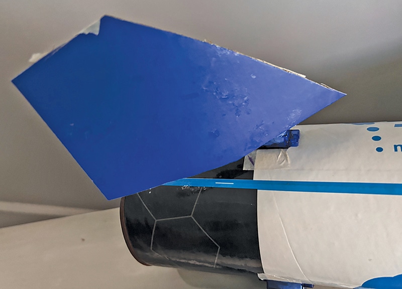
Attach a fin securely to the servo horn (servo shaft). Ensure that the fin is firmly fixed and can rotate smoothly without obstruction. Once the fin is attached, mount the servo motor inside the rocket body so that the fin protrudes through the fin slot (see Fig. 6) and can move freely. Repeat the same procedure for the remaining fins, where applicable.
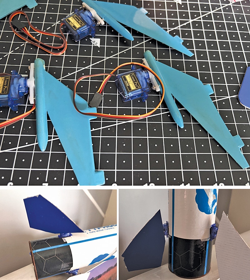
Although some rocket designs use multiple independently controlled fins for improved flight control and stabilisation, this system uses only the bottom fins with servo actuation to keep the design simple, economical, and easy to reproduce. More advanced designs may employ additional servo-controlled fins to achieve greater manoeuvrability and improved flight stability.
EFY note. Fin size, shape, and placement depend on the rocket design. The fin assembly shown here is intended for demonstration and testing only. Optimise the fin design and its position based on the simulation results to achieve the best flight performance.
Testing
The system is now ready for testing. Begin with software and telemetry testing.
Power on the rocket to enable its Wi-Fi access point (AP). Connect a laptop or smartphone to the rocket’s Wi-Fi network, then open the web dashboard to monitor telemetry data in real time. Fig. 7 shows the rocket fins moving for stabilisation.
The web dashboard displays the stabilisation system in operation. As the rocket body is tilted or moved, the control fins automatically adjust their positions using the PID algorithm to counter the movement and stabilise the rocket.
The dashboard displays real-time information, including altitude, IMU data, barometric pressure, temperature, PID output, fin positions, and other sensor readings.
Precautions
- Conduct all tests only in a vacant ground with a minimum clear space of 150 metres in all directions.
- Ensure the rocket is properly assembled and that all safety procedures are strictly followed under the guidance of an experienced engineer.
- To begin with, test only the rocket’s software, electronics, telemetry, and stabilisation systems. Do not perform a full flight test.
- Before conducting any test, carefully review the NASA model rocket safety guide
- Failure to follow these instructions may result in serious injury, property damage, or legal consequences.
Ashwini Kumar Sinha, an IoT and AI enthusiast, is Tech Journalist at EFY.