
Building a robot is an effective way to understand embedded systems, control logic, and real-world electronics integration. This system demonstrates a Bluetooth-controlled mobile robot built around the low-cost STM32 Blue Pill microcontroller. It features an OLED display, four BO motors, and Li-ion batteries for power.
The robot can be controlled wirelessly from a smartphone via Bluetooth, while the OLED displays real-time system information such as connection status, eye animations, and battery level.
With its low-cost design, compact size, and simple connections, the robot can serve as an educational and experimental platform for students and hobbyists. It demonstrates the practical implementation of key concepts such as GPIO interfacing, serial communication, motor-driver control, display interfacing, and battery-powered operation.
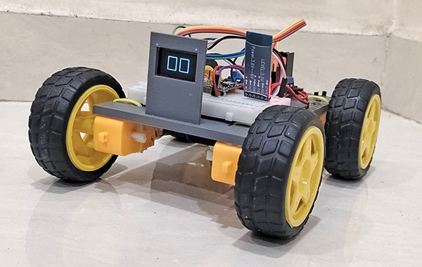
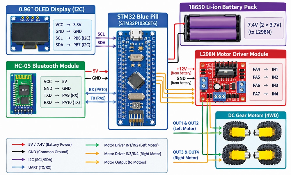
The system can be further enhanced by integrating sensors, obstacle detection, and other robotic applications. Fig. 1 shows the authors’ prototype, while Fig. 2 shows the wiring diagram of the system. The components required to build the system are listed in the Bill of Materials table.
| Bill of Materials | ||
| Name | Specification | Quantity |
| STM32 | Blue Pill board | 1 |
| Battery | Li-ion, 3.7V, 2000mAh-2500mAh | 2 |
| Battery holder | Two-cell battery holder | 1 |
| L298N | Motor driver | 1 |
| HC-05 | Bluetooth module | 1 |
| BO gear motor | Dual shaft 200rpm | 4 |
| OLED display | 0.96-inch (2.4cm) I2C | 1 |
| Switch | SPST | 1 |
Circuit and working
Fig. 3 shows the circuit diagram of the Bluetooth-controlled robot using the STM32 Blue Pill. The system is built around an STM32F103C8T6-based Blue Pill board, an L298N motor driver, an HC-05 Bluetooth module, four dual-shaft 200rpm BO geared motors, a 0.96-inch (2.4cm) I2C OLED display, two 3.7V, 2000mAh-2500mAh Li-ion batteries, a two-cell holder, and an SPST switch.
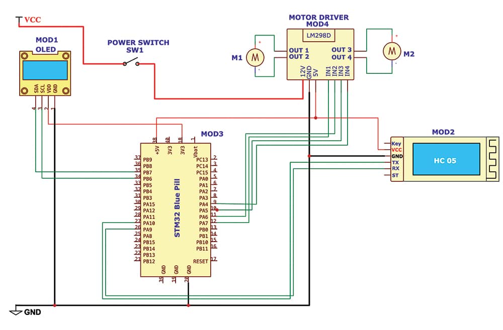
The robot is designed as a compact, four-wheel mobile platform with a 3D-printed chassis that provides stability and balanced load distribution. Four BO geared motors are mounted on the wheels to provide sufficient torque. The STM32F103C8T6 operates at 72MHz and manages Bluetooth commands, motor-control logic, and OLED display updates. Since the microcontroller cannot drive the motors directly, an L298N H-bridge motor driver controls them. This arrangement allows the robot to move forwards, backwards, left, right, and rotate through 360 degrees.