
Thermal cameras are used for PCB fault detection, solar-panel inspection, engineering thermal analysis, and body-temperature monitoring. However, good-quality thermal cameras are often expensive and relatively bulky.
This system provides an affordable, highly portable option for basic thermal imaging and analysis. It uses the AMG8833 8×8 infrared sensor to capture thermal data and can be upgraded to higher resolution by replacing it with an MLX90640 or MLX90641. A GC9A01 round display provides real-time thermal video with colour mapping, making temperature variations easy to view.
Measuring just 3.5cm in diameter, the compact, battery-powered unit is small enough to carry like a keychain. It can measure the temperature of a person or object and help identify abnormal hotspots in electronic devices, overloaded components, poor solder joints, and other sources of excessive heat. It can also be used for basic PCB thermal analysis and routine thermal checks.
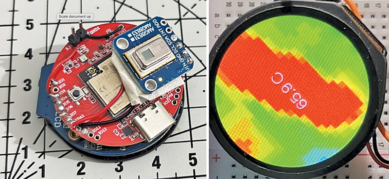
Fig. 1 shows the author’s prototype, including the rear and top views, along with a size comparison against a scale. The components required to build this system are listed in the Bill of Materials table.
| Bill of Materials | |||
| Name | Designator | Description | Quantity |
| IPS/LCD display | U1 | GC9A01 IPS display | 1 |
| ESP32-S2 board | U2 | IndusBoard COIN V2 or any ESP32-S2-based board | 1 |
| Thermal sensor | U3 | AMG8833 thermal sensor module | 1 |
| 3.3V power supply | — | 3.3V Li-Po battery, 800mAh | 1 |
Circuit and working
Fig. 2 shows the circuit diagram of the thermal camera based on the IndusBoard Coin V2. The circuit consists of four main components: the GC9A01 round IPS display (U1), the IndusBoard Coin V2, an ESP32-S2-based coin-sized board (U2), and the GY-AMG8833 thermal sensor (U3).
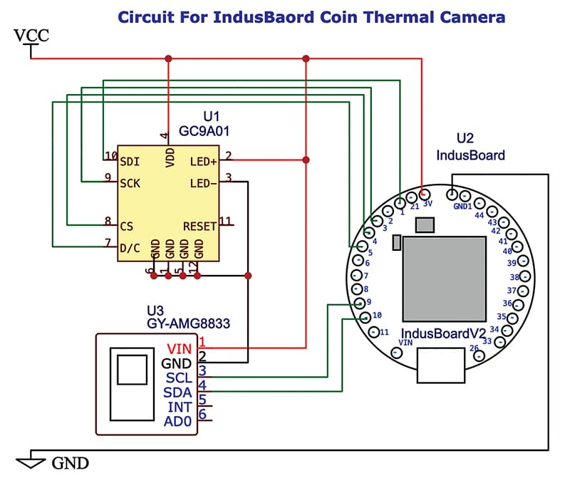
The GY-AMG8833 thermal sensor (U3) contains an 8×8 infrared array that measures temperature at 64 points simultaneously. It communicates with the IndusBoard Coin V2 through the I²C interface, with SDA and SCL connected to GPIO 8 and GPIO 9, respectively. The sensor’s VIN is connected to the 3.3V supply, while GND is connected to the common ground. The INT and AD0 pins are left unconnected in the basic configuration.
The IndusBoard reads the 64 temperature values from the AMG8833 and processes them to generate a thermal image. The temperature values are mapped to different colours according to their levels, producing a thermal-image effect. The processed data is then sent to the GC9A01 round TFT display (U1) through the SPI interface using the SDI (MOSI), SCK, CS, and D/C signals. The recommended SPI connections shown in the schematic are Pin 1 to CS, Pin 3 to SCK, Pin 4 to SDI (MOSI), and Pin 5 to D/C.
The GC9A01 display presents the resulting thermal image in real time. Its LED+ pin is connected to VCC and LED− to GND for backlight operation. The display communicates with the IndusBoard through the SPI interface using the assigned GPIO pins.
Power is supplied through common 3.3V (VCC) and GND lines shared by all three modules. Thus, the overall signal flow is AMG8833 thermal sensing→I²C→IndusBoard processing→SPI→GC9A01 thermal display. The IndusBoard can also perform additional temperature analysis or transmit the measured data to other applications if required.
Alternatively, any other ESP32-S2-based board can be used if a compact size is not required. The corresponding circuit is shown in Fig. 3. The functionality and code remain the same; only the circuit connections need to be modified according to the ESP32-S2 board used, as shown in Fig. 3. All other components and the overall working principle remain unchanged.
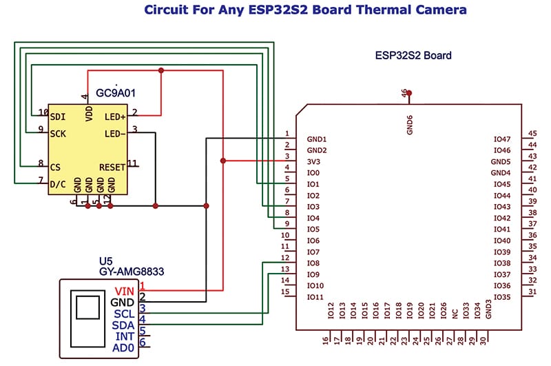
As shown in Fig. 3, an ESP32-S2 board can be used to interface the GC9A01 round TFT display and GY-AMG8833 8×8 thermal sensor. The GC9A01 uses SPI, with SDI, SCK, CS, and D/C connected to GPIO 4, GPIO 3, GPIO 2, and GPIO 0, respectively. The AMG8833 uses I²C, with SCL and SDA connected to GPIO 9 and GPIO 8, respectively. Powered from 3.3V, the ESP32-S2 processes the 64 temperature readings into a colour-coded thermal image and displays it in real time on the GC9A01.
Construction
After uploading the source code to the IndusBoard and completing the connections, the GC9A01 round display is mounted on the top side of the IndusBoard Coin, while the AMG8833 sensor is mounted on the rear side. This keeps the overall size to 3.5cm. Alternatively, the same circuit can be built on a breadboard, as shown in Fig. 4, which shows the prototype of the thermal camera on a breadboard.
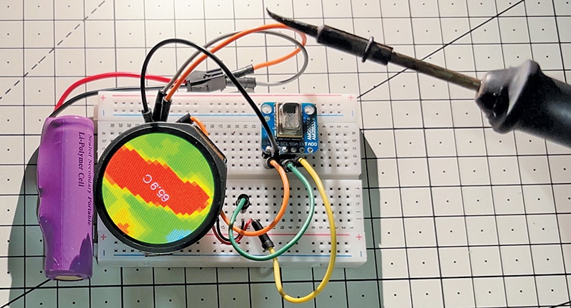
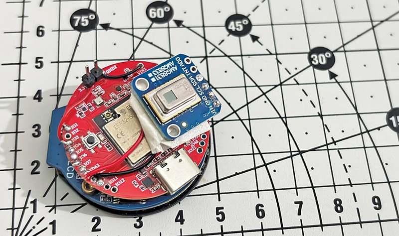
When powered, the ESP32-S2 on the IndusBoard reads the 8×8 temperature array from the AMG8833 over I²C, processes the data, applies colour mapping, and continuously sends the thermal image to the GC9A01 display over SPI. The result is a real-time thermal video shown on the round screen along with the centre temperature reading. Fig. 5 shows the assembled and soldered thermal camera, along with a size scale for comparison.
Software/Coding
The code is developed using the Arduino IDE with the TFT_eSPI and Adafruit AMG88xx libraries. Both libraries can be installed through ToolsLibrary Manager. Next, the User_Setup.h file in the TFT_eSPI library needs to be configured according to the display driver and connected GPIO pins. Since the display uses SPI, the required GPIO pins can be assigned according to the circuit. For this system, the GC9A01 display driver should be selected and the pins configured accordingly.
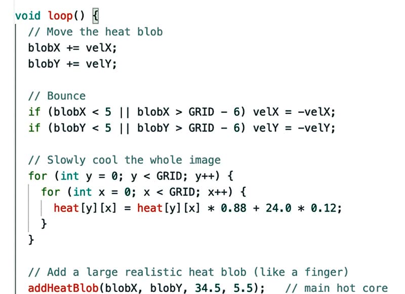
During operation, the code continuously reads the 8×8 temperature data from the AMG8833, maps the readings to a cold-to-hot colour gradient (blueyellowred), and displays the resulting thermal image in real time. Fig. 6 shows a code snippet for mapping the thermal grid data to display colours.
Testing and troubleshooting
After uploading the code, the device can be powered using a 3.7V Li-Po battery or USB. The round display should light up and show a live thermal image within a few seconds. Placing a finger or hand in front of the AMG8833 sensor should produce a yellow-to-red heat region on the screen along with the centre temperature reading.
Common issues and solutions
1. Display remains blank
Check the SPI connections (CS, SCK, MOSI, and D/C) and verify that the correct GPIO pins are defined in the User_Setup.h file of TFT_eSPI. Also ensure that the GC9A01 driver is enabled.
2. No thermal image or fixed blue screen
Check the AMG8833 I²C connections (SDA and SCL) and verify that the Adafruit AMG88xx library is installed correctly.
3. Wrong or inverted colours
Adjust the MINTEMP and MAXTEMP values in the code. A typical range for human-body detection is 20°C to 38°C.
4. Incorrect temperature reading
Ensure that the sensor is uncovered and properly facing the target. The centre temperature is calculated from the middle pixels of the 8×8 array.
5. Device resets or does not power on
Check the battery voltage and VCC/GND connections. Poor power connections can cause random resets.
Once the thermal image appears correctly and responds to heat sources, the camera can be used for basic applications such as PCB fault detection, temperature monitoring, and thermal analysis.
Ashwini Kumar Sinha, an IoT and AI enthusiast, is Tech Journalist at EFY.