

Solve Elec, as the name says, is a software that makes the task of dealing with electrical designs a lot easier. Right from the circuit stage, analysis, to finally getting a report, Solve Elec is your friend to help and correct the multitude of ideas developing in your mind. Read on to know what Solve Elec has to offer to make designing easier and fun.
An all-in-one workstation
It is often comfortable to have the various elements of the design stage on one screen, right next to each other. Especially in complex circuits where each click of the mouse leads to different scenarios, one needs to shift between the various pop-up windows to figure out what is happening where.
The workstation of Solve Elec is designed to hold the basic necessary tabs, neatly arranged in columns on a single screen. Be it the design tools for creating, running and editing a circuit, a window showing its properties or the measurement setup that helps you monitor your circuit—each has its own space that can be customised. Easy to see, easy to access!

Modes that replicate current behaviour
Right at the start, mode of operation has to be selected. This turns out to be the most important step as not all components can be ported between alternating current (AC) and direct current (DC) modes, which only seems logical after all.
In DC mode, components from switches to integrated amplifiers are available to you, while voltage and intensity sources drive a constant value for the entire duration of the simulation.
In AC mode, voltages, intensities and potentials are sine waves of the same frequency; the waves represented as complex values in circuit properties. Methods of complex analysis are exploited to find a solution for the circuit that can only contain components operating in linear mode, so that the sine wave is preserved.
Solve Elec Features aiding effective analysis
A graph is one of the easiest means of analysing relationships between data, and the graph plotter in Solve Elec lets you plot quantities associated with components defined by metres or by formulae. The customisable graph asks you to define a parameter from among the component-associated quantities, while plotting metre or formula values on both axes.
There are also curve functions that help draw intensity and tension curve values on a graph. The plotted graph uses different colours to highlight different state functioning, like linear, active and saturation mode for a transistor’s characteristics, each of which is described by the graph legend. You can turn off the legend to make modifications to the graph.
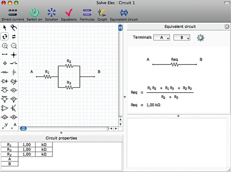
For any circuit consisting of linear components, its equivalent circuit, as seen from any two points, can be obtained using Solve Elec. From the equivalent resistance of a set of resistors to Thevenin equivalent circuit, data is provided along with the formulae involved. For AC voltages and currents, oscilloscope feature can be exploited to view the signals as if on a real instrument.
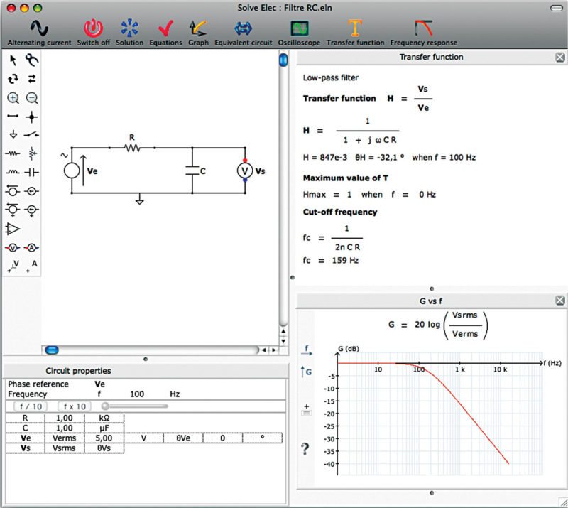
 What happens when frequency is changed. No electrical analysis is complete without analysing the circuit’s frequency response. Solve Elec lets you trace this response using transfer functions and gains obtained for circuits working on an AC source. The necessary condition is that the circuit must contain a single input voltage source and only one voltmeter defining the output voltage.
A transfer function tool, when initiated, checks the circuit, analyses it and displays the results on the transfer function pane. For a resistor-capacitor (RC) filter circuit, the pane contains details like definitions of the function, values of the various parameters involved and finally ending with the cut-off frequency of the designed filter. Corresponding frequency response can be linear or logarithmic, and phase relations can also be displayed.
Set up with care, measure with ease
Solve Elec comes with a well-defined set of measuring instruments like the ammeter and the voltmeter, which can be included at necessary regions in the design. Computed quantities are accompanied by their values and formulae used to calculate these, in a window called Solution. Calculated using a formal calculus engine, this comes in handy while manually verifying equations, drawing graphs and so on.
As always, potential reference is taken with respect to the ground terminal, and nodes can be named using point labels. Also available is a probe that can be used to measure the potential at a point, be it on a wire or at a terminal.
How about automating to reduce effort. Of course, the idea behind simulating a circuit is not only to verify its correctness, but also to compute parameters that cannot be measured directly. These could be something as simple as power dissipated by a resistor, or intense like the loading effect at the output.
Manually calculating these for each iteration of the design is even more tedious. By defining a formula for each of the necessary calculations and assigning it newly-defined quantities in the circuit, computations are automatically performed each time the circuit is solved.
If complex and time consuming, a wait window appears as a warning to you alongside an option to stop the process. The solution can check errors in signs, issues with homogeneity or incorrect application of standard laws like Kirchoff’s rules. It also spells out the states of circuit components, if different, along with explicit values of every parameter discussed.
Well, of course, the solution tab is a quick and sure-shot way of finding out if the circuit is solved. While the power-off button can turn the circuit off, any action like asking for a solution, equation or graph turns it on again.
Creating the circuit is easy
With tools at one’s disposal, all that is needed is to choose the required components, add these to the drawing and orient these. Either the US or the European norm can be selected under software preferences. Components and wires cannot overlay each other, so components have to be aptly placed or re-sized; although wires can cross over each other with or without contact.
The software keeps checking the placement as and when each action is performed, and refuses to initiate a rotate or move if there is chance of overlap. Components are notated by a letter followed by numbers, which specifically have to be different for every instance of switches, diodes, amplifiers and transistors.
A reverse tool helps set right the direction of current for power supplies or electrolytic capacitors by simply reversing its terminals. The tool also comes in handy to turn the circuit switch on and off, which otherwise has to be done using buttons from the main menu. Almost all actions have an equivalent keyboard shortcut that can be exploited for faster operation.
Complex is simple. Complex circuits often require certain common design elements that are repeatedly used. Such elements can be created and exported to keep these saved. The next time these need to be used, menus help import the mini circuit and begin with the bigger design right away.
Editing the properties of components in the design easily enables a change in parameters. Any change is automatically reflected in the display window; a displayed graph is automatically recomputed for the new value and redrawn, saving a lot of trouble.
Making it easier to adapt to change. Solve Elec offers a comprehensive set of components to choose from. Properties of each of these can be configured to meet various functionalities, while staying within circuit limitations. Any component that exceeds its maximum rating simply blows up on the screen during simulation. As real as it gets, is it not?
Handle with caution. Set the threshold value for the diode to zero for operating under ideal conditions. The same concept is extended to light emitting diodes, with the threshold now responsible for the colour of the light emitted.
Whenever an op-amp appears in the circuit, Solve Elec uses its ideal model to perform circuit analysis. Care needs to be taken with respect to the operating region of the amplifier, as once saturated, output voltage ceases to be sinusoidal and analysis is abandoned. Transistors being non-linear components are not allowed in AC designs.
Reporting the easy way
The hardest part of any design activity is the documentation that follows. A report menu in Solve Elec panel provides an easy method of selecting and combining various elements displayed in the main window, to create a readymade report. This could include details like circuit drawings, graphs, formulae and circuit properties. There is also a provision to add editable text fields and images from other applications, and you can even have a report plan, which is similar to the contents page in manually-created ones.
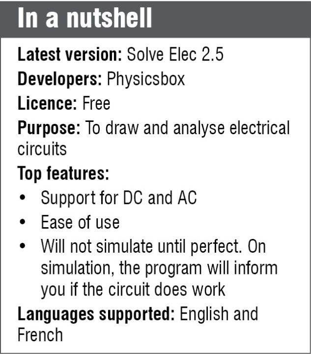
Version 2.5 of Solve Elec is free to use and supports both MAC and Windows. Easy to get acquainted with and comfortable to work on, this is a useful software for beginners or advanced users in the domain of electrical engineering.
Download software: click here
Priya Ravindran is M.Sc (electronics) from VIT University, Vellore, Tamil Nadu. She loves to explore new avenues and is passionate about writing


