


Presented here is a 0-50V, 1A variable power supply that has  been designed using positive-adjustable voltage regulator LM317 IC. This IC normally generates voltages in the range of 1.2V to 25V, but here it produces 0 to 50V with a current of 1A. The circuit used increases the upper voltage from 25V to 50V and decreases the lower voltage from 1.2V to 0V.
Variable power supply circuit
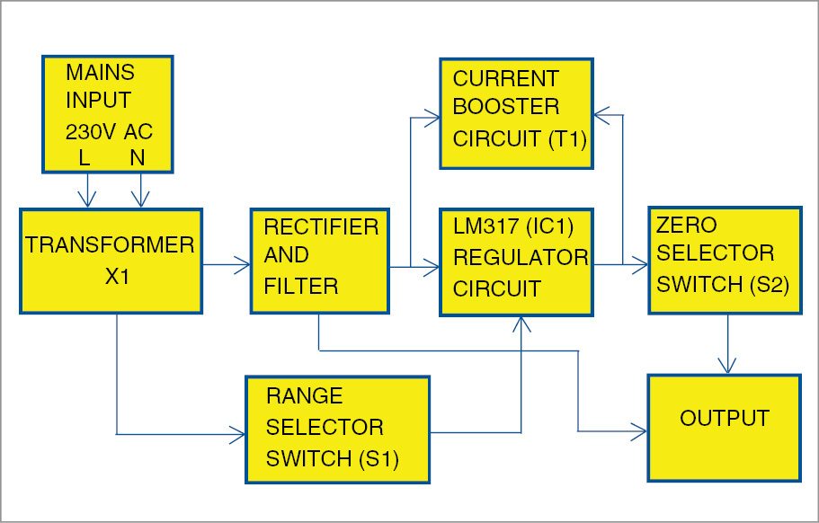
Fig. 1 shows the block diagram of the variable power supply. Mains input is connected to transformer X1. Output of the transformer is given to LM317 via rectifier diodes. Final output is provided by LM317 and transistor T1.
Heart of the circuit is LM317. Data sheet of LM317 IC states that it can produce voltages between 1.2V and 37V with a maximum current of 1.5A. LM317 has an internal reference voltage of 1.25V. This voltage is reflected in the output and is set as the lower-limit voltage.

Maximum differential voltage between input and output should not exceed 40V to operate within safe limits. For this, voltage drop of 3V is maintained between input and output. To obtain maximum voltage with LM317, input should be 40V. So, if LM317 is fed with a maximum of 40V, output will be 40V-3V=37V
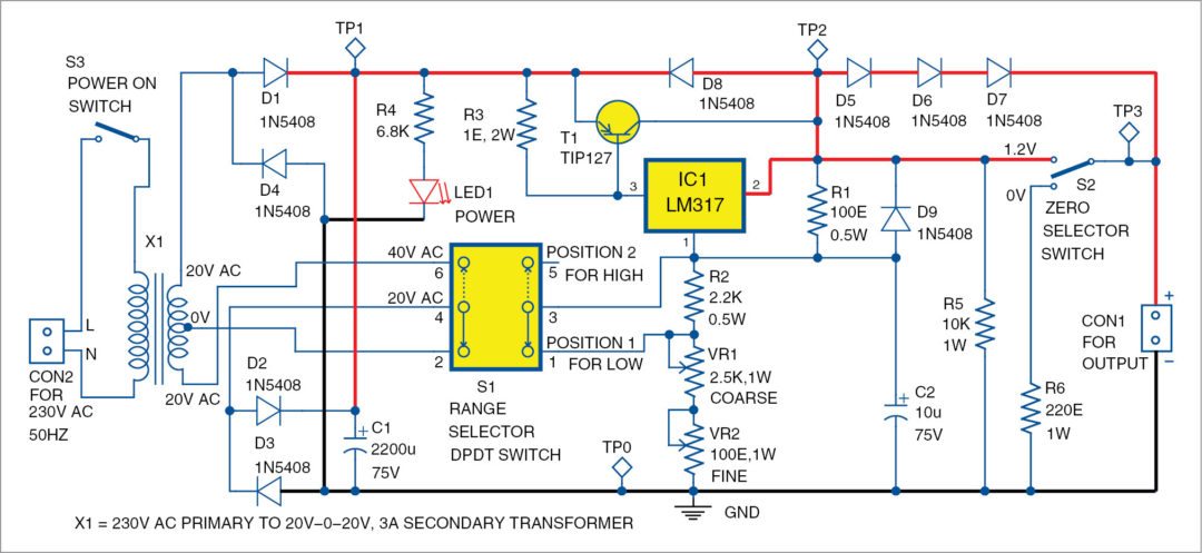
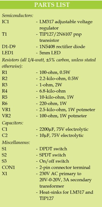
Circuit diagram of the 0-50V, 1A variable power supply is shown in Fig. 2. It is built around step-down transformer X1, bridge rectifier comprising D1 through D4 (1N5408), adjustable voltage regulator LM317 (IC1), power transistor TIP127 or 2N6107 (T1) and diodes 1N5408 (D5 through D9).

The circuit is centred around LM317, whose output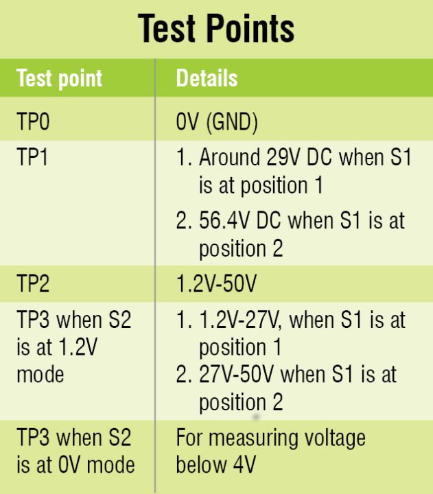 depends on resistors R1, R2, VR1 and VR2. A centre-tapped transformer (X1) with 230V AC primary to 20V-0-20V, 3A secondary is chosen, whose centre-tap point is at 0V and voltage between both ends of secondary windings is 40V AC. So, voltage between the centre tap and either end of the secondary winding is 20V AC. One side (half) of the secondary (20V AC) windings is connected to anode of D1 and cathode of D4.
Secondary of X1 is connected to the bridge rectifier through range selector switch S1. When S1 is in position 1, its pins 3 and 1 as well as pins 4 and 2 are shorted. This results in connecting 20V AC to the bridge rectifier. The 20V AC is rectified, producing around 29V DC, which is connected as input to LM317 IC.
Resistor R2 is shorted through pins 1 and 3 of S1, connecting VR1 and VR2 at pin 1 of IC1. Output depends on the positions of VR1 and VR2. VR1 is configured as a coarse voltage-adjusting knob and VR2 is configured as fine voltage-adjusting knob. By varying the potmeters (VR1 and VR2), voltage output is varied in the range of 1.2V to 27.8V (at TP2).

With S1 in position 2, its pins 1 and 3 are opened and pins 4 and 6 are shorted. This results in connecting 40V AC to the bridge rectifier. Thus 40V AC is rectified, producing around 56.4V DC, which is connected as input to LM317. Shorting of R2 is now opened. Due to a series connection of R2 with VR1 and VR2, lower limit of the output voltage is increased from 1.2V to 27V. At position 2 of S1, differential voltage of LM317 is 56V-27V=29V. By varying potmeters VR1 and VR2, in position 2 of S1, voltage is varied in the range of 27V to 50V at TP2.
At output stage, three diodes (D5 through D7) are connected in series to obtain 0V output, assuming each diode voltage drop of 0.5V (that is, 3 x 0.5 = 1.5V) nullifies output residue voltage of 1.2V from LM317. Zero-volt selector switch S2 works in 0V or 1.2V mode. When it is in 0V mode, effect of diodes in series is present and so 0V output is obtained. When the switch is in 1.2V mode, the three diodes are shorted and actual output of 1.2V is passed on to the output.
Resistor R6 helps series diodes D5 through D7 give better regulation at voltages lower than 4V. If you are operating above 4V, it is better to use 1.2V mode, as presence of series diodes affects the regulation of the power supply. R3 is used to switch on T1 when current exceeds 600mA through LM317.
Construction and testing
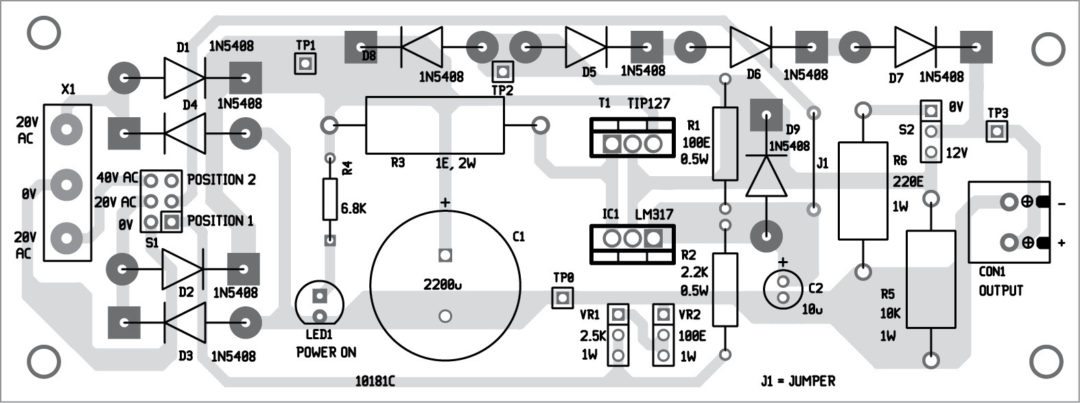
A single-side PCB pattern for the 0-50V, 1A variable power supply is shown in Fig. 3 and its component layout in Fig. 4. After assembling all components on the designed PCB, enclose it in a suitable box in such a way that 230V AC mains can be connected easily.
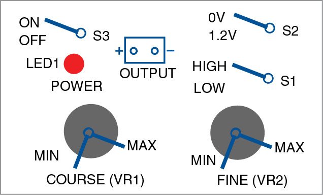
Fix the output terminals on front side of the cabinet along with switches, potmeters and LED1 as shown in Fig. 5. Connect jumper J1 externally on the PCB. Fix switches, LED1 and potmeters VR1 and VR2 with proper labels on the front panel. Verify the test points table before using the circuit.
IC1 and current-boost transistor TIP127/2N6107 should be placed on suitable heat-sinks. S1 is marked as the range-selector switch, while S2 is marked as zero-selection switch. Use 2-pin terminal connectors for output connection. VR1 is labelled for coarse adjustment and VR2 for fine adjustment.
LED1 is used as a power-on indicator. D8, D9 and C2 are used for protection. At 50V, power supply can supply a maximum current of 1A. Choose a good-quality transformer (X1) to support IC1.
Note.
1. Switch S2 to 1.2V when output requirement is above 4V.
2. Switch off AC mains power while switching S1 to high range. Wait for a few seconds until power LED1 goes off.
3. Do not short output terminals.
4. Use proper heat-sinks for IC1 and T1.
5. During testing we used a 20V-0-20V, 2A transformer and output was in the range of 29V, 1.5A to 50V, 220mA when S1 was at position 2 and S2 at 1.2V. Similarly, output was 12V, 800mA to 21V, 100mA when S1 was at position 1 and S2 at 1.2V.
Download PCB and component layout PDFs: CLICK HERE
K. Murali Krishna is a former faculty of Aditya Engineering College, Surampalem, Andhra Pradesh. Presently, he is working as telecom technical assistant, BSNL Rajahmundry, Andhra Pradesh


Very good power supply.
Thank you for your feedback.
Nice one…
Thank you for your feedback.
thank you Mr for this circuit >>
could you help me with your TP using ?
or what do you mean by TP?
thank you …
Thanks for the feedback! TP stands for Test Point.
Kindly provide design in detail..
Thank you sir. Excellent job. We do not need lm317hv ic
ow can u use the LM317 and TP127 to reduce it to 1A
I established low led lights design Using 12 volts Step-down transformer and controlling lm317 transistor, lights from transformer and on other side I connected Arduino Uno with 5 volts charger but the program is executed in uno board but transformer side light was not blinking my doubt is both grounds are commonly not connected is that problem, my fear is about short circuit please give any answer shall I connect power supply both common grounds thank you.
Hello sir/Madam,
I am looking to build a Bench variable power supply using 24 0 24v 5amps Transformer, Do you have any circuits around this, I could not find any circuits, Kindly help me with the same.
thanks and regards
We do not have such project published right now but will be publishing similar project very soon