


I am building a 4-channel touchless switchboard. Arduino Uno, as the heart of the project, surrounded by four ultrasonic sound sensors, offers a simple, low-cost, and novel solution. The switches can be turned on and off alternately by just placing a hand next to the ultrasonic sound sensors on the device, without touching.
We recently developed a gesture-controlled contactless switch.
Circuit and working
Fig. 1 shows the circuit diagram of the 4-channel touchless switchboard. It comprises four HC-SR04 ultrasonic sound sensors (SEN1-SEN4), a four-channel relay board (RM1), and an Arduino Uno board (Board1).


The microcontroller in the Arduino Uno board receives the switching signals from the sensors and the program code sends the signals to the 4-channel relay module and thereby switches on/off the devices. The ultrasonic sound sensor HC-SR04 is used to sense the switching action.
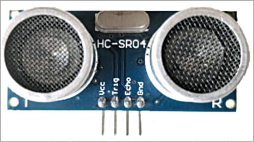
Pin details of the HC-SR04 ultrasonic sensor are shown in Fig. 2. It has following four pins:
VCC: +5V DC
Trig: Trigger (input)
Echo: Echo (output)
GND: GND
The sensors can be easily interfaced with Arduino Uno. When a hand is placed about 5cm from the sensor the program in Arduino reads the signal and the relay is energised to perform the switching action. When the hand is again placed near the sensor, the Arduino again reads the signal and the relay is de-energised to toggle the switch from its previous position. Similar action is performed with all other ultrasonic sound sensors.
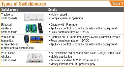
Table 1 shows the comparison between various types of switchboards that are generally available. Table 2 shows the Arduino Uno pin connections with components.
4-channel relay board
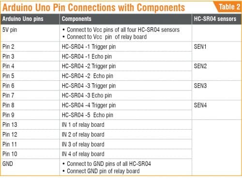
Fig. 3 shows a 4-channel relay board. This is a low-level, 5V board whose each channel consumes 15-20mA driver current. It can be used to run various appliances that consume large current as it is equipped with high-current relays operating under 250V, 10A AC or 30V, 10A DC. It has a standard interface that can be controlled directly by the microcontroller.
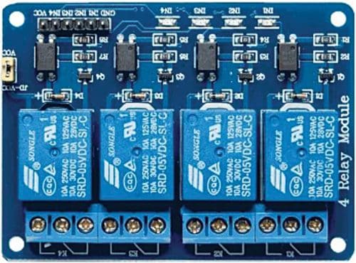
This module is optically isolated from high voltages for safety and has four SPDT relays.
Software
The software program fourchan.ino is loaded into the internal memory of Arduino Uno. The program is simple and easy to understand. Comments are given at the end of each command line.
The following need to be defined in the code first:
- Echo and trigger pins of the ultrasonic sound sensor
- Four relays’ pins
- Intermediate variables for relay operation
- Variables for all the four sensors
Next, a void setup ( ) function should be created. The corresponding pins should be initialised as inputs and outputs. Then serial communication should be initiated. The serial communication has nothing to do with the project, it is used for just analysing the program on a monitor.
The loop( ) function allows the program to change and respond. It is used to actively control the Arduino Uno board. Activate the Echo sensor. Calculate the distance and perform the switching action on/off. Pass on the switch condition to the relay. Write the above code for all the other three sensors and relays as well.
Construction and Testing
The circuit requires a 12V, 1A DC power supply. Connect the module as shown in the circuit diagram. Maintain some distance between the four Echo sensors so that their operation does not affect the adjacent sensors.
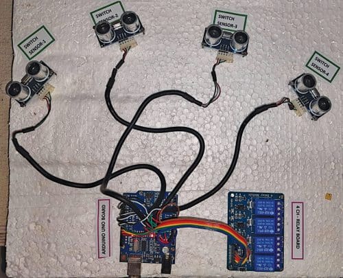
A PVC switchboard box can be used to enclose the Arduino Uno and the relays board. Connect the AC appliances in accordance with the specifications of the relays. The connection of phase (L) and neutral (N) wires is shown in the circuit diagram. The author’s prototype is shown in Fig. 4.
Note: The Arduino Uno board and HC-SR04 sensors are highly sensitive, so handle carefully. You need to bring your hand near the sensor slowly and remove it slowly.
Caution. Take proper precautions while handling AC mains. Novice experimenters are advised to consult an expert before making AC mains connections with the relays.
Download Source Code
K. Murali Krishna is working as junior engineer, BSNL, Rajahmundry, Andhra Pradesh. He is an electronics enthusiast, circuit designer and technical writer.

I like this!
Thank you for your comment.
Could you plz share the simulation of the project if possible