


 433MHz radio frequency (RF) modules are widely used in different wireless projects and products. Normal range of most RF transmitter and receiver modules is below fifty metres. This RF Range Extender circuit can increase the range of operation to almost double the normal range, depending on make of the RF module and antenna used.
Circuit and working
The circuit diagram of the 433MHz amplifier is shown in Fig. 1. It is built around transistors C2570 (T1) and 2N5109 (T2), and a few other components.
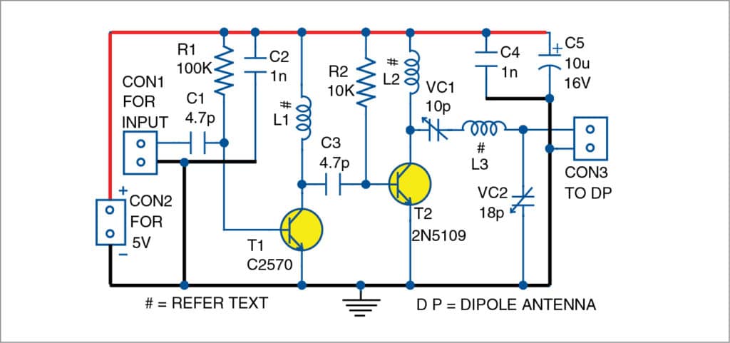
Connector CON1 provides convenience for connecting antenna of the RF transmitter module. CON2 is used for connecting 5V DC power supply, while CON3 is used to connect the dipole antenna.

The circuit is a two-stage ultra high frequency (UHF) amplifier. Both T1 and T2 are wired as class A amplifiers. Maximum range can be obtained by using a dipole antenna (DP) with a good quality co-axial cable.
T1 is an NEC-make C2570 transistor. T2 is a UHF medium-power transistor 2N5109, available in metal package.
VC1 and VC2 are variable trimmer capacitors. Readily-available Philips-make trimmers (22p) can be used. Inductor L1 can be made with three turns of 24 SWG wire and air core of 4mm diameter. Coil L2 can be made with two turns of 24 SWG wire over 4mm dia air core. Coil L3 should have just one turn of 24 SWG wire over air core of 4mm diameter. SWG wire should be enameled copper wire.
Construction and testing
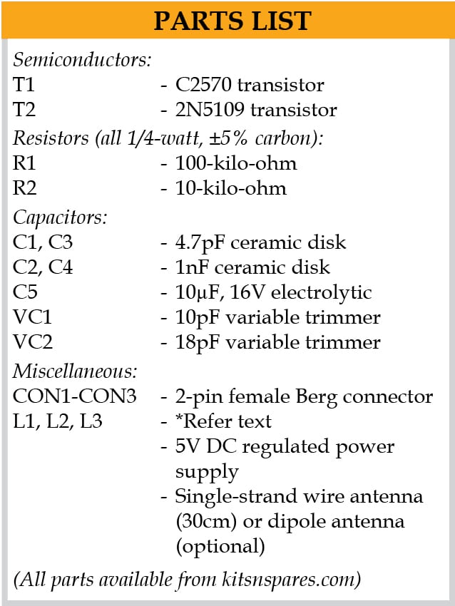
A PCB layout of the 433MHz RF range extender is shown in Fig. 2 and its components layout in Fig. 3. After assembling the circuit on the PCB, connect 5V across CON2. Connect 433MHz RF transmitter module’s output to CON1 input of this amplifier.
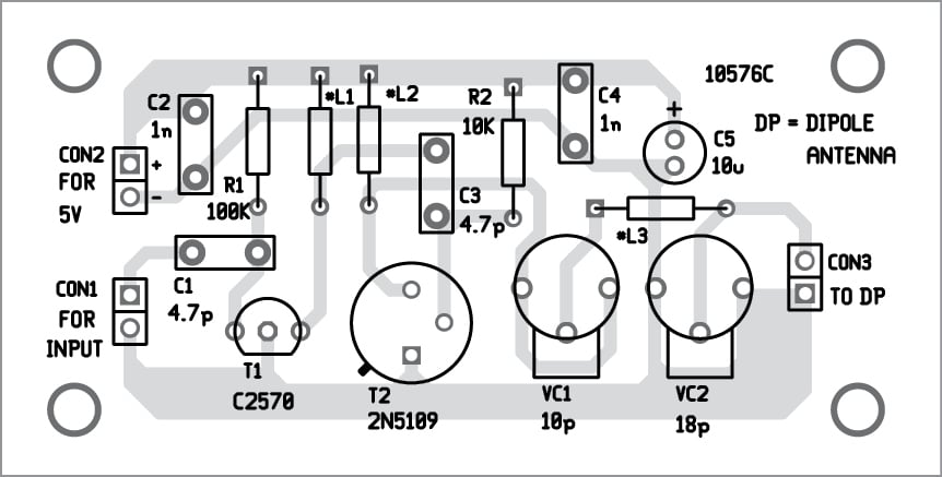
Download PCB and Component Layout PDFs: click here
For initial testing, in place of DP, connect a single-strand wire antenna (around thirty centimetres in length) to CON3. Now, feed a signal pulse at data input pin of RF transmitter module and check signal at data out pin of RF receiver module. Slowly move the receiver unit away from the transmitter unit to check range of operation.
Pradeep G. is an electronics hobbyist and old contributor to EFY
Read other interesting Electronics Projects: click here


When I connect the data output of the transmitter module to the shown circuit’s input the receiver module will not receive data pulses. Is it because the transmitter module gets overloaded and gets detune. I have reduced the 4.7pF input to 1pF. But no results. Please advise me.
That is wrong. You should connect ANT. pin of transmitter module to CON1. The capacitor value 4.7pF used is working fine.
What is power output into 50ohm?
I think you are talking about the power output to the feedpoint impedance of coaxial cable. It is in milliwatt. However, as mentioned in the article, a hook up wire was used during testing instead of coaxial cable. The setup for coaxial cable should be different.
Yes. Generally the power output is tested by termination the coaxial cable into a 50ohm resistor or dummy load and then measuring the peak RF voltage. Range of a transmitter gets doubled for every 4x increase in power. 433MHz module has an output of 10mW or so. I think the amplifier boosts it to 100mW or so.
Yes. Generally the power output is tested by termination the coaxial cable into a 50ohm resistor or dummy load and then measuring the peak RF voltage. Range of a transmitter gets doubled for every 4x increase in power. 433MHz module has an output of 10mW or so. I think the amplifier boosts it to 100mW or so.
Don’t get caught by your postal authorities using this, the fines are quite steep and dependent what country you are in you might end up in jail. Unless you have a ham radio license. the usage of this is prohibited in nearly every country in the world.