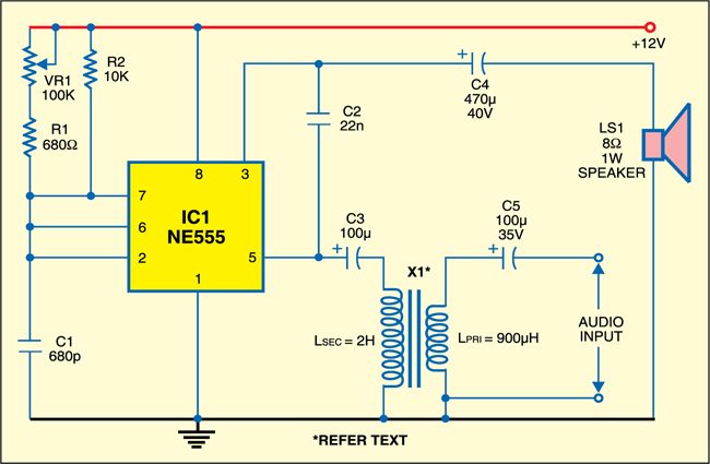
The “555” integrated circuit is a general-purpose timer useful for a variety of functions. In this 555 audio PWM project, we explore its use as an astable multivibrator. The ubiquitous 555 timer IC handles audio signals in its own pulse-width modulation (PWM) way. Here, the 555 IC works in astable mode. The switching frequency can be varied from 65 kHz to 188 kHz. Selection of PWM frequency depends on the amplitude of the input signal as well as the load impedance. By adjusting VR1, you can ensure comfortable listening with low audio distortion.
Working explanation
In pulse-width modulation, the carrier frequency’s pulse width varies as a function of the amplitude of the input audio signal. Feedback capacitor C2 ensures faithful reproduction of the audio signal. An output L-C filter is the common approach for a reasonable rejection of the carrier frequencies. For simplicity, it is omitted here. Moreover, the speakers cannot respond to the high-frequency signal. They respond to the average DC level modulated with the audio signal that we feed in from the input. Of course, the audio quality is not as good as that of a professional system, but it would be definitely an amazing experience to listen audio through a 555 chip with room-filling volume.
555 Audio PWM circuit

Impedance matching at both the input and output is important. So an input-impedance matching transformer (X1) is used to match the headphone output of a standard CD player to the input of the 555 amp. 8-ohm, 1W speakers were used as the load. If designed properly, PWM amplifiers could give a performance similar to conventional amplifiers. Even higher efficiency and effortless bass are possible.
EFY note. While testing this circuit at EFY lab, we had used Supertronix KEC make matching transformer X1, and the input to the circuit was the audio output taken from the computer’s headphone out terminal.


What is the approximate output power with 8 ohms operating at 12V. For stereo can we use LM556 dual timer?