


 This air ioniser is built around an NE555 timer IC which is configured in astable mode.
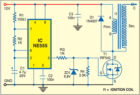
The circuit is powered by a 12V battery, which also provides power supply to the ignition coil. The ignition coil used here is the same as used in scooters and bikes.
Fig. 1 shows the circuit of the air ioniser. The 146 Hz output of IC NE555 is fed to an n-channel MOSFET (T1), which acts as a switch. T1 is switched at the rate of 146 Hz, producing a high voltage at the high-tension (HT) terminal of the ignition coil. The high voltage difference between the HT terminal and the body of the coil produces spark in the air gap to ionise the air.

Assemble the circuit on a general-purpose PCB and enclose in a suitable cabinet. Care should be taken while handling the ignition coil (shown in Fig. 2) to avoid the risk of shock.
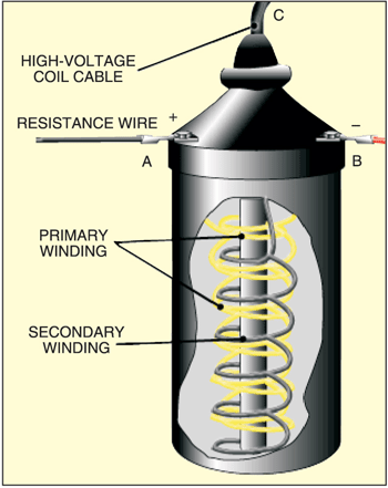
Normally, a thick high-voltage cable with metal strip at both the ends is used in the ignition coil to extend connection for the actual application. The metal strip should be brought close (about one centimetre) to the body of the ignition coil so that the air between these is ionised. House the arrangement in a closed enclosure such as an airtight container to observe the ionising effect. The closed container should have two openings to allow the air inside and pass out ionised air to the room. For the purpose, a small air pump such as the one used in aquariums can be used.
Good design, but will it produce negative ions.
Kindly elaborate your query.