


In the world of electronics and embedded systems, the use of a joystick and an Arduino Uno board has many possibilities for developing control systems, especially for disabled individuals with no hands. Creating a joystick with Arduino-based control for five applications can significantly improve the quality of life and independence of the disabled.
The goal of this project is to develop a hands-free control system that allows individuals without hands to independently operate various devices and systems within their homes.
By using this joystick with Arduino-based control, users can manipulate the joystick with their elbow, chin, foot, or any other body part to send control signals to the Arduino. The Arduino then sends these signals to switch on or switch off different appliances.

| Parts List | |
| Semiconductors: | |
| IC1 | – LM7805, 5V voltage regulator |
| IC2-IC6 | – LM555 timers |
| T1, T2, T8-T10 | – 2N2219 NPN transistors |
| T3-T7 | – BC547 NPN transistors |
| BR1 | – 1A bridge rectifier |
| D1-D6 | – 1N4007 rectifier diodes |
| LED1-LED6 | – 5mm LEDs |
| Resistors (all 1/4-watt, ±5% carbon): | |
| R1-R10, R13- | |
| R16, R20-R31 | – 1-kilo-ohm |
| R11, R12, | |
| R17-R19 | – 100-kilo-ohm |
| Capacitors: | |
| C1 | – 1000μF, 35V electrolytic |
| C2-C6 | – 4.7μF, 16V electrolytic |
| Miscellaneous: | |
| CON1-CON5, | |
| CON7-CON12 | – 2-pin connectors |
| CON6 | – 5-pin connector |
| BOARD1 | – Arduino Uno |
| RL1-RL5 | – 5V SPDT relays |
| APPL.1- | |
| APPL.5 | – 230V AC appliances |
| X1 | – 230V AC primary to 9V, 500mA secondary transformer |
| – Joystick | |
The system allows for the customization of control parameters, making it adaptable to the user’s specific needs and preferences. This joystick can enhance the user’s comfort and convenience by providing control over essential home systems. It can also be expanded to integrate with a wide range of smart home devices, making it a central control hub for multiple applications.

This hands-free smart home control system showcases the potential of joystick and Arduino-based control in improving the daily lives of individuals with physical disabilities, offering them greater independence and control over their environment. A prototype of the joystick is shown in Fig. 1.
Arduino-based Appliance Control Circuit
Fig. 2 shows the circuit diagram of the joystick with Arduino-based control for up to five appliances for the disabled. The circuit is built around a 230V AC primary to 9V, 500mA secondary transformer (X1), a bridge rectifier (BR1), an Arduino Uno board (Board1), a joystick (connected across CON6), 5V voltage regulator LM7805 (IC1), five LM555 timer ICs (IC2 through IC6), five BC547 transistors (T3-T7), five 2N2219 transistors (T1, T2, T8-T10), five 5V SPDT relays (RL1-RL5), the five 230V AC appliances to be controlled (APPL.1 through APPL.5), and a few other components.
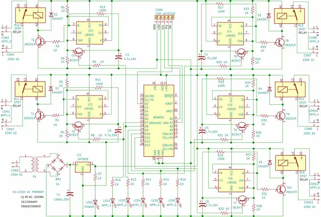
The joystick is essentially a combination of two potentiometers for the X and Y planes, respectively. It reads the voltage through two potentiometers and provides an analog value to the Arduino, which changes as the joystick shaft moves.
Here we are interfacing the joystick with the Arduino Uno to control five LEDs based on the joystick’s movement. This joystick also has a push button that can control one more LED (LED2).
Four LEDs (LED3 through LED6) represent the direction of the joystick shaft movement. A glowing LED1 indicates that the power supply is available and the circuit is enabled. Joysticks come in various shapes and sizes, and the one used here is shown in Fig. 3.
A joystick module typically provides analog outputs, which change as the joystick is moved in different directions. Its movement can be interpreted in two axes: X-axis and Y-axis. A potentiometer represents movement in each axis, and their midpoints are driven out as Rx and Ry. These potentiometers act as voltage dividers when the joystick is on standby.
When the joystick is moved, the voltage on each pin changes depending on the direction, representing four directions of joystick movement based on two ADC outputs.
The joystick module used here also has two potentiometers inside it: one for X-axis movement and another for Y-axis movement. Each potentiometer receives 5V from the Arduino. As the joystick moves, the voltage value changes, and the analog value at pins A0 and A1 also changes.
From the Arduino, we read the analog values for the X and Y axes and turned on the LEDs accordingly. A push-button switch on the joystick module controls LED2 in the circuit.
There are five toggle circuits built around LM555 (IC2 through IC6), all identical. Let us take a look at IC2, which toggles relay RL1 when you press the joystick. Pins 2 and 6, the threshold and trigger inputs, are held at half the supply voltage by the two 1k resistors R3 and R4.
When the output of IC2 at pin 3 is high, capacitor C2 charges through the 100k resistor R11 and discharges when the output is low. When the joystick is pressed, the voltage from capacitor C2 is applied to pins 2 and 6 via transistor T3, causing the output to change to the opposite state.
When the joystick is released, the capacitor again charges to the new level at the output (pin 3).
Arduino Joystick based Appliance Control Working
The working of the circuit is simple. When 230V AC is applied across CON5, power LED1 turns on, and the circuit is enabled. To operate the first appliance, you press the joystick, and the first appliance (APPL.1) will turn on.
When you press the joystick again, APPL.1 will turn off, and LED2 will briefly blink. To operate the second appliance, you move the joystick to the left, and the second appliance (APPL.2) turns on.
Moving the joystick left again will turn off APPL.2, with LED3 briefly blinking. The same process applies to the third, fourth, and fifth appliances, controlled by joystick movements in different directions, each associated with a respective LED.
Joystick Arduino Project Code
The source code is written in the Arduino IDE platform, version 1.8.5. Before uploading the given sketch to the Arduino Uno board, ensure that you select the correct board and port. Then upload the sketch file ‘Joycon.ino’ to the board. Fig. 4 shows a screenshot of the source code.

Arduino-Based Joystick Control PCB Design
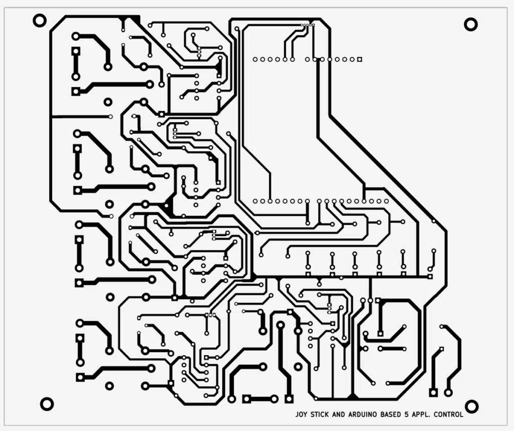
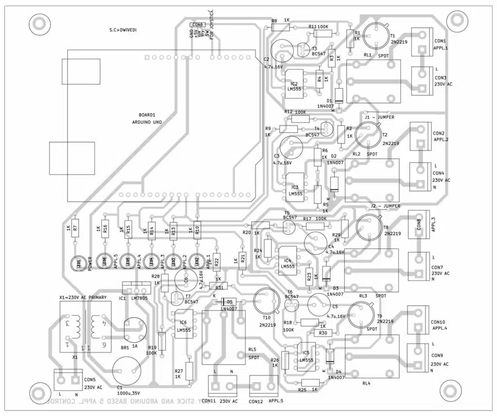
After uploading the code to the Arduino and connecting the components as per the circuit diagram, you can now control the LEDs with the joystick. You can momentarily turn on (blink) the five LEDs in each direction according to the joystick shaft’s movement. An actual-size, single-side PCB for the project is shown in Fig. 5, and its component layout in Fig. 6.
Also Check: Interesting Arduino Projects
Assembly and Testing
Assemble the circuit on the PCB and enclose it in a cabinet. Connect all the connectors (CON1 through CON6) at the rear side of the cabinet and LEDs (LED1 through LED6) at the front side. LED1 indicates power, while LED2 represents control for the first appliance (APPL.1). LED3-LED6 corresponds to appliances APPL.2 through APPL.5 based on the x and y movement of the joystick. Connect the joystick module across CON6 using external jumper wires and connect 230V AC across CON6.
After assembling the circuits on PCB boards, power on the circuit. Observe the power LED1; it should be on. LED2 on the receiving board blinks whenever the joystick is pressed. Test the blinking of the other LEDs by using joystick movements in different directions (left, right, up, and down).
If all LEDs respond correctly to the joystick movements, everything is working as expected. Then connect the appliances to the respective relays and connect 230V AC.
Bonus: You can watch the video of the tutorial of this DIY project at this link.
S.C. Dwivedi is an electronics enthusiast and circuit designer at EFY
