


Here we have designed an Automatic Water Tank Filling System using Arduino.
In India, many houses have two sources of water to fill the rooftop water tank. These are underground water storage tanks and municipal water supply. Based on the availability, the rooftop tank is filled either with municipal water or with the underground tank water with the help of an electric water pump.
Filling the overhead tank by manually switching on the electric water pump requires frequent monitoring of the water level inside the tanks. It also results in the wastage of water when it overflows from the overhead tank. This project aims to fill the overhead tank automatically without any human intervention.

The proposed system determines the level of water in the rooftop tank, checks the availability of sufficient water in the underground tank or municipal supply, and then fills the overhead tank to the desired level using any of the two available sources. The filling of the tank through municipal supply is controlled through a solenoid valve and the water pump is controlled through a contactor.
The decision making is done through a microcontroller in Arduino Nano and electronic devices like BJT, MOSFETs, and diodes. The working of the project can be explained through two cases that utilise different water sources based on their availability.
POC Video Tutorial In English:
POC Video Tutorial In Hindi:
Case 2. Water level in overhead tank is below 100% and municipal supply is available. In this case, water will be filled through the municipal supply to the tank’s full capacity. A solenoid valve will be used to stop filling the tank after the tank is fully filled.

Fig. 1 shows the basic design idea of project while circuit diagram of the automatic water system is shown in Fig. 2. The electronic and mechanical components required to make this project are listed in the Bill of Material table.
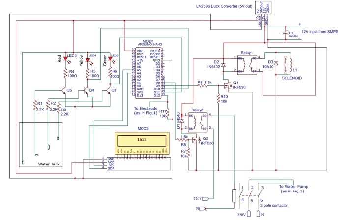
Automatic Water Tank Filling System Circuit Diagram
The circuit is built around Arduino Nano (MOD1), 16×2 LCD with I2C/IIC interface (MOD2), three BC548 transistors, two IRF530 MOSFETs, and a relay.
Working
The availability of municipal supply is detected by the two electrodes drilled into the pipe and connected to Arduino. The gap between the electrodes acts as a hindrance to the flow of current (as resistance). When the municipal water is available, the current starts flowing through the electrodes, which is detected by the microcontroller in Arduino.
The flow of water from the municipal supply is controlled through a solenoid valve and the water pump is used to fill the water from underground storage tank to rooftop tank. Two one-way valves are used to prevent reverse flow of water. The two water supplies are merged to a single outlet through a ‘T’ connector.
The water level is determined by the three BC548 BJT transistors that act as switches. The bases of the BJTs are connected to the electrodes dipped into the tank at different levels (50%, 75%, and 100%) through resistors. When the water level reaches an electrode then the corresponding transistor turns on and thus the LED connected to the transistor also turns on. The collector pins of two transistors are also connected to the digital pins of the Arduino to further define the logic of the circuit.
| Bill of Material | |
| Components | Quantity |
| Arduino Nano (MOD1) | 1 |
| 16×2 LCD display with I2C/IIC interface (MOD2) | 1 |
| 12V, 2A SMPS | 1 |
| LM2596 DC-DC buck converter (manually set to 5V) | 1 |
| Solenoid valve (L1) | 1 |
| 10A, 240V, 2-pole contactor | 1 |
| IRF530 n-channel MOSFET (Q1, Q2) | 2 |
| BC548 BJT (Q3, Q4, Q5) | 3 |
| 1N5402 diode (D1, D2) | 2 |
| 10A10 diode (D3) | 1 |
| Green, yellow, and red LED | 1 Each |
| 100-ohm resistor (R4, R5, R6) | 3 |
| 1.5k resistor (R8, R9) | 2 |
| 2.2k resistor (R1, R2, R3) | 3 |
| 10k resistor (R7, R10) | 2 |
| 1×3 JST connector for the water level probe | 1 |
| DC jack to connect solenoid valve | 1 |
| 220V 3-pin connector for water pump | 1 |
| AC 220V, 10A 3-pin panel mount plug socket for 220V input | 1 |
| 10A rated switch | 1 |
| 5V, one changeover relay | 2 |
| MECHANICAL COMPONENTS | |
| 1HP household water pump | 1 |
| PCV pipe (cut to different sizes as per diagram) | 1 metre (min) |
| One-way valve | 2 |
| Elbow joint | 2 |
| Female copper adaptor | 4 |
| Steel hose nipple | Steel hose nipple |
The 16×2 LCD connected to the Arduino Nano through I2C displays the status of water supply and water pump.
The solenoid valve is controlled via a relay. The relay is controlled by the IRF530 MOSFET. The gate pin of the MOSFET is connected to the digital pin D9 of Arduino Nano through a resistor. The resistor connected between the gate of the MOSFET and the ground acts as a pull-down resistor. A flyback diode is connected in parallel to the coils of the relay to protect the MOSFET from high voltage created by collapsing magnetic fields.
The water pump can be directly controlled through the relay but due to high inrush current of the pump, the contacts of the relay can easily get damaged. Hence, a contactor similar to a relay is used, but it operates on 220V AC and has a bigger and heavier metal contacts that do not damage easily. The contactor is controlled through the same relay-MOSFET system as explained above. The gate pin of the MOSFET is connected to digital pin D8 of Arduino Nano.
The Arduino Nano is powered with a 5V input, which is achieved through a buck converter connected to the 12V supply. A 4700µF capacitor is connected to the 12V power supply to act as a low-pass filter.
[signinlocker id=”87626″]
Water Tank Filling System Code
Arduino Uno IDE is used here. In the Arduino code, the behaviour of the hardware components is defined based on the methodology mentioned earlier.


The variables GreenState, YellowState record the states of the transistors connected to green and yellow LEDs. Since the output is 180-degree phase shifted, ‘HIGH’ corresponds to a transistor being off and ‘LOW’ corresponds to the transistor being on. Fig. 3, Fig. 4, and Fig. 5 show snapshots of the source code.
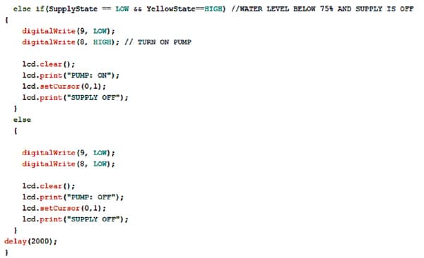
The data from this variable is further used to define if-else logic to control the solenoid and the water pump. The LCD used to display the state of the two water sources is controlled using I2C communication. The libraries, Wire.h and LiquidCrystal_I2C.h, are utilised for I2C communication with the LCD. After each loop, a delay of 2000ms is added in the execution of the code.
You can download the complete code from electronicsforu.com. After getting the code ready, upload the code to Arduino by selecting the right port and board.
Construction and Testing
You can assemble the circuit on a small general-purpose PCB. But before assembly do not forget to upload the source code into Arduino Nano. The project has two parts, the mechanical assembly, and the electrical circuit. The pipe mechanical assembly is shown in Fig. 6.
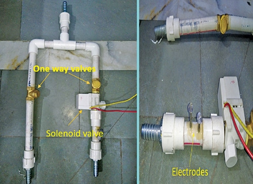
The mechanical part of this project can be constructed using a 1.3cm (½-inch) dia PVC pipe and corresponding fittings. The following fittings may be required:
- Elbow connector
- ‘T’ connector
- Female copper adaptor
- Steel hose nipple
Two metal nails are inserted into the PCV pipe to act as electrodes to detect the availability of municipal supply, as mentioned earlier.
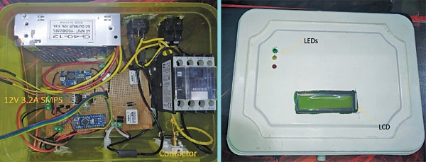
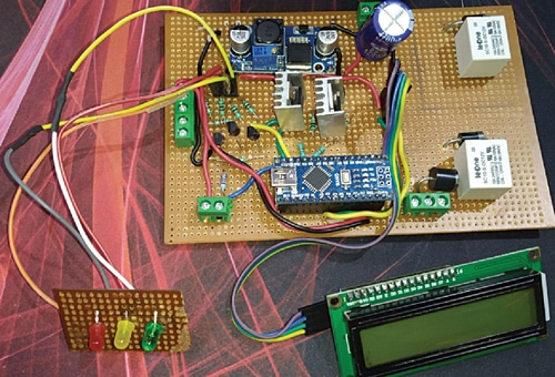
The complete circuit is soldered on a perf board as per the circuit diagram shown in Fig. 2. Terminal blocks are utilised to connect the 12V DC power, level probe, electrode, and solenoid. The three LEDs are soldered on a separate perf board and mounted on the enclosure. Heat-sinks are used for the MOSFETs to dissipate heat generated during their operation.
The complete assembly is shown in Fig. 8, Fig. 9, and Fig. 10.
The circuit is enclosed inside a plastic enclosure with the lid used to mount the LCD and the LEDs. Along with the circuit board, the 12V, 3.3A SMPS and the contactor are also fitted inside the enclosure.
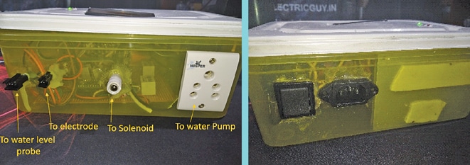
On the sides of the enclosure, different connectors are mounted to connect the sensing elements and devices, as shown in Fig. 9. These connectors are:
- JST connectors to connect the water level probe and the electrodes
- DC jack to connect the solenoid valve
- 220V, 3-pin connector to connect water pump
- AC 220V, 10A rated 3-pin panel-mount plug and socket for 220V input
- A 10A rated switch
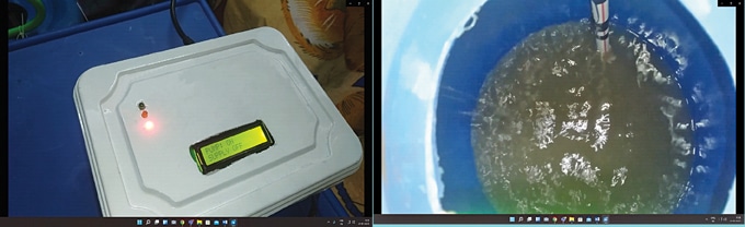
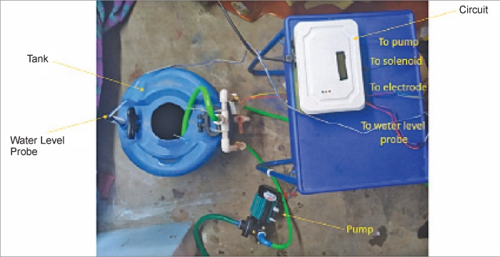
The mechanical assembly is mounted vertically on the overhead tank and through a small hole the water level probe is inserted in the tank. A 0.5HP water pump is connected to the mechanical assembly, which will be controlled through the circuit. Working and testing of the circuit is shown in Fig. 11 through Fig. 12.
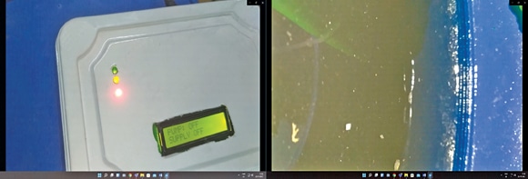
Case 1: Water level is below 75% and municipal supply is not available
- Water is filled through the pump and the red LED is on.
- Water filling stops when 75% water level has reached and now the yellow LED switches on.
Case 2: Water level is below 100% and municipal supply is available
- Water is filled through the municipal supply and the yellow LED is on.
- Water filling stops (solenoid valve turns off) when the tank becomes full and the green LED
switches on.
Improvements Possible
The project is by no means perfect and can be improved as per requirements. For instance, the water level probe can be further enhanced by adding a grid of metal contacts to precisely measure the water level.
Water remaining in the municipal supply lines, even when the supply is not available, sometimes gives false data about the availability of the supply. It can be improved by
enhancing the mechanical design or by using a pressure sensor instead of a metal electrode.
Download Source code
Naman Tanwar is an IoT and electronics enthusiast who is pursuing his engineering from the School of Electronics Engineering, Vellore Institute of Technology in Tamil Nadu
[/signinlocker]
Sir, In the Bill of Material diodes D1 & D2 are mentioned as 1N5402. But in
Fig. 2: Circuit diagram diode 1N540 is used for D1.
Which one is correct?
Its 1N5402.