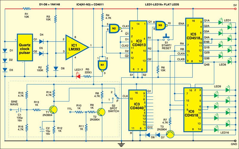
Here is a simple circuit that precisely measures the frequency in BCD format. The circuit is built around dual comparator LM393 (IC1), dual D-type flip-flop CD4013 (IC2), binary ripple counter CD4040 (IC3), dual NAND gate CD4011 (IC4), dual up-counter CD4518 (IC5 and IC6) and a few discrete components.
The range of the circuit can be increased to a few MHz by incorporating a simple divider stage of CD4040 between the output of the coupler (shown within dotted line) and the input of gate N3. Feed the sinewave or TTL frequencies to be measured at the points shown within the dotted lines.
The precision timing required to measure the frequency is derived from a quartz clock. Dual CD4013 flip-flops (IC2) are arranged such that when start switch S1 is pressed momentarily, the one-second pulse from the quartz clock enables gate N3 of IC4 for one second. The input sinewave or TTL pulses are counted by counters IC5 and IC6. Counters IC5 and IC6 count up to four-digit numbers, which are displayed on 16 green flat LEDs (LED1 through LED16) in BCD format.

Note that when gate N3 is enabled for counting, the display LEDs are cut off by transistor T3 to avoid any noise that may affect the counting. The display is enabled once gate N3 is disabled after one second elapses.
The circuit works off 5V DC. The power supply required for the quartz clock circuit is provided by using a series combination of three diodes (D1 through D3).
Assemble the circuit on a general-purpose PCB and enclose in a suitable cabinet. Fix the LEDs such that the frequency can be read easily. Connect suitable terminals for frequency inputs and power supply.