This project can be used to control multiple electrical appliances on any floor from any floor of a multistory building that has up to six floors. It uses a controller area network (CAN) bus and Arduino Uno to control the appliances. CAN bus was designed for multiplex electrical wiring required in automobiles, but it can also be used in many other applications such as this one.
In a modern car there are hundreds of sensors and actuators, all of which communicate with each other independently and with the central computer/processor. All these interconnections would require at least a thousand metres of wiring. The CAN bus does away with all these multitude of wires and instead runs only one twisted shielded pair of wire (bus) from one end to the other. All the sensors are connected to this bus at their nodal points.
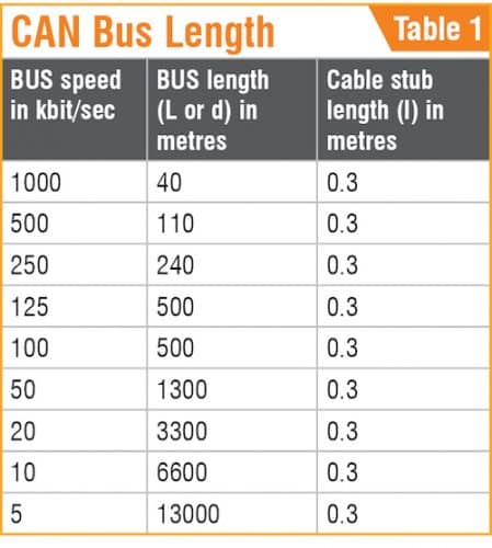
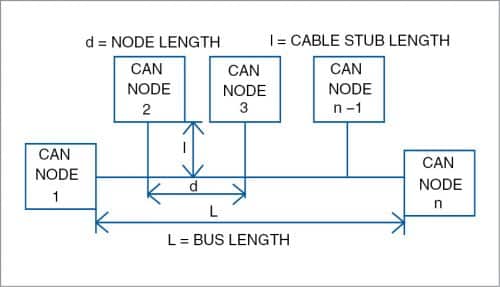
A typical CAN bus setup is shown in Fig. 1. The number of nodes can vary from 0 to 130 on a single bus and length of bus can also vary from a few metres to a few kilometres (see Table 1).
Unlike RS485 Modbus, where only a handful of 32 nodes can be used, CAN bus can have up to 130 nodes, of which practically 90 nodes can be used comfortably. When node-to-node length is more than 300 metres, a CAN bus repeater may be used for flexibility and less data loss.
Circuit and working
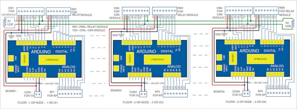
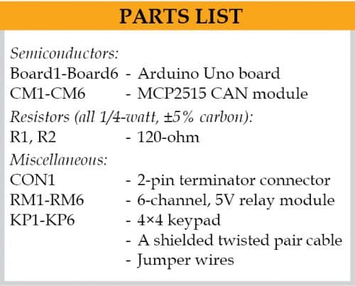
The basic connections for the project are shown in Fig. 1. For a six story building, it requires six Ardunio Uno boards (Board1 through Board6), six CAN modules (CM1 through CM6), six 5V relay modules (RM1 through RM6), six 4×4 keypads (KP1 through KP6), two 120-ohm termination resistors, and a few other components.
Fig. 1: A typical CAN bus setup
CAN bus for switching. Imagine a situation where all the switches of a typical hotel lobby are soft switches. The control pulse of each switch is given to a digital input-output pin for the relay to get energised and switch on the light or air-conditioner. Such a system is quite easy to develop using a 5-volt relay connected to an Arduino board.
A typical CAN bus can transmit 5-digit data very easily over the bus from one end to the other, which can be intercepted by all the nodes that are connected to the common bus. The numerical data can be a combination of any five digits (any 5-digit number) such as 12345, 23456, 25401, or 25480. These data digits get converted to switching signals in this project, which is the key to this multistory switching system.
Fig. 2: Circuit diagram of CAN bus for a multistory building
Switching signals using 5-digit number
Arduino Uno and a 4×4 keypad having eight data lines are used for generating the switching signals in this project. All the eight data lines (four rows and four columns) of the keypad are connected to A0, A1, A2, A3, A4, A5, D2, and D3 pins of Arduino Uno. Note that D0 and D1 being the UART pins of the Arduino Uno, they are not used for the keypad or relay module.
For connecting the CAN bus module with Arduino, you require SPI interface and an additional CS (chip select) pin. That means, the D10 through D13 pins of Arduino are used up for the CAN bus interface. So, we are left with six pins (D4 through D9) of Arduino for switching the relay modules.
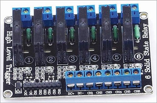
Six-channel, 5V relay modules are easily available in the market (see Fig. 3). Each of the remaining six pins of Arduino can be interfaced to each channel of the relay module. These relay modules can be used for 240V, 2A loads and for switching electrical appliances such as lights and fans.
Fig. 3: Typical 5V, six-channel solid-state relay module
Switching algorithm
Each switching signal includes five digits that are sent along the CAN bus. In this project, we assigned the node IDs like 253, 254, and 255. The relays are numbered as 0 through 9. The relay signals are identified as 41, 40, 51, 50, 61, 60, 71, 70, 81, 80, 91, 90, etc.
Therefore, to switch on the first relay connected to D4 pin of Arduino, the 5-digit switching signals on CAN bus node ID 253 will be 25341#. Here, the ‘#’ key from the keypad is used as ‘Enter’ button for ‘end of command’ in the algorithm. To switch off the relay, you need to send 5-digit signal 25340# across the CAN bus.
Similarly, you can send 25391# and 25390# signals across the bus to switch on and switch off the sixth relay, respectively.
Assuming there is one CAN bus node on each floor in a six story building, this circuit will let you control up to six relays (and the devices connected to them) on any floor from any floor of the house. For example, if you wish to control all six relays on fourth floor that has CAN bus ID 254 (say, node 4), from the third floor having CAN bus ID 253 (node 3), you need to do the following:
First upload the Arduino code ‘CAN_multistory253.ino’ for third floor into Arduino Uno (Board3) and ‘CAN_multistory254.ino’ for fourth floor into Arduno Uno (Board4). When you enter 25341# keys from keypad (KP3), relay connected to D4 of Board3 energises and the load connected to its contacts switches on. When you enter 25340# keys from KP3, the relay de-energises and the load switches off.
Similarly, suppose you want to control the relays connected to node ID 254 from node ID 253. Enter 25441# from keypad (KP3); the relay connected to D4 pin of Arduino Uno (Board4) energises and the load connected to its contact switches on. Similarly, when you press 25440# from KP3, the relay de-energises.
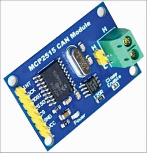
CAN bus transceiver built on MCP2515 chip used in the project is shown in Fig. 4. It has an SPI bus male pin connector. Its 2-pin terminal connector is for connecting CAN bus—high (H) and low (L) cable wires. The cable should be of good quality shielded twisted pair copper type. A 120-ohm termination resistor at the end of the bus is essential, else it will weaken the signal through self-radiation.
Fig. 4: CAN bus module
Software
The software is written in Arduino programming language (Sketch) and compiled using Arduino IDE software. Software is just CAN_multistory.ino for all the nodes. Just include the node numbers like 253, 254, 255, 256, 257, 258, and 259 in the code, then upload the code to the corresponding Arduino nodes. This software is typically for an Arduino Uno-driven circuit.
As an example, we have used two Arduino source codes, CAN_multistory253.ino and CAN_multistory254.ino, for third and fourth floors, respectively. You can, like-wise, add the node numbers in the codes for the other Arduino Uno boards on respective floors.
Before compiling and uploading the code, you need to include CAN_Bus_headers.zip and keypad.zip libraries in Arduino IDE.
Switching algorithm using Arduino Mega board
An Arduino Mega board has more digital pins to accommodate more switches, but the CAN bus has a limitation of five numeric digits. To tackle this problem, we reduce the node ID number to two digits (10, 11, 12, 13, …99) instead of three digits (253, 254, 255, etc).
Therefore, while using Mega board, you can use a CAN bus ID, say 25. Then the switching signal with 25301# will switch on the relay connected to the digital pin D30 of Arduino Mega. Similarly, 25300# will switch off the relay connected to D30. You can thus have many more switches on Mega.
Construction and testing
Assemble the circuit shown in Fig. 2 on a breadboard. Connect all the six nodes via 2-pin cable: one for H cable and another for L cable. Make sure that the earth line (shielded) is also connected. Do not forget to connect 120-ohm resistor across H and L of CAN module. For short distance communication between two nodes, 120-ohm termination resistor is not required.
One important point to prevent unknown operation on the node: Suppose one node is to be stopped from operation. But if it is unplugged from the bus, it will reset the bus and its node number will vanish from the system, which is not desirable.
So, the solution is to just disconnect the CS pin from the bus. It will remain on hold condition in that position. If some relays are already on, these will remain on. Similarly, if some relays are off, these will remain off. To restore, just reconnect the CS pin in the bus, which will start the normal operation again.
Somnath Bera is an Assistant General Manager (AGM) at NTPC Limited, bringing extensive industrial experience in thermal power systems along with strong expertise in electronics, IoT, AI, and embedded systems. His multidisciplinary background enables him to bridge large-scale industrial applications with modern digital technologies.
Alongside his leadership role in the energy sector, Somnath is a prolific contributor to Electronics For You, where he shares practical, project-driven insights for engineers, makers, and technology enthusiasts. His work focuses on real-world implementations, combining hardware and software to create impactful solutions.
He is also known for his hands-on demonstrations and tutorials, which simplify complex concepts and make advanced technologies accessible to both hobbyists and professionals. His contributions reflect a unique blend of deep technical knowledge, industry experience, and a strong commitment to knowledge sharing.


 This project can be used to control multiple electrical appliances on any floor from any floor of a multistory building that has up to six floors. It uses a controller area network (CAN) bus and Arduino Uno to control the appliances. CAN bus was designed for multiplex electrical wiring required in automobiles, but it can also be used in many other applications such as this one.
In a modern car there are hundreds of sensors and actuators, all of which communicate with each other independently and with the central computer/processor. All these interconnections would require at least a thousand metres of wiring. The CAN bus does away with all these multitude of wires and instead runs only one twisted shielded pair of wire (bus) from one end to the other. All the sensors are connected to this bus at their nodal points.
A typical CAN bus setup is shown in Fig. 1. The number of nodes can vary from 0 to 130 on a single bus and length of bus can also vary from a few metres to a few kilometres (see Table 1).
This project can be used to control multiple electrical appliances on any floor from any floor of a multistory building that has up to six floors. It uses a controller area network (CAN) bus and Arduino Uno to control the appliances. CAN bus was designed for multiplex electrical wiring required in automobiles, but it can also be used in many other applications such as this one.
In a modern car there are hundreds of sensors and actuators, all of which communicate with each other independently and with the central computer/processor. All these interconnections would require at least a thousand metres of wiring. The CAN bus does away with all these multitude of wires and instead runs only one twisted shielded pair of wire (bus) from one end to the other. All the sensors are connected to this bus at their nodal points.
A typical CAN bus setup is shown in Fig. 1. The number of nodes can vary from 0 to 130 on a single bus and length of bus can also vary from a few metres to a few kilometres (see Table 1).
 Unlike RS485 Modbus, where only a handful of 32 nodes can be used, CAN bus can have up to 130 nodes, of which practically 90 nodes can be used comfortably. When node-to-node length is more than 300 metres, a CAN bus repeater may be used for flexibility and less data loss.
 So, the solution is to just disconnect the CS pin from the bus. It will remain on hold condition in that position. If some relays are already on, these will remain on. Similarly, if some relays are off, these will remain off. To restore, just reconnect the CS pin in the bus, which will start the normal operation again.
