


Using this fan speed controller circuit you can control the speed of 12V DC fans used in cars. The circuit is built around timer 555, which is wired as an astable multivibrator.
Fan speed controller circuit
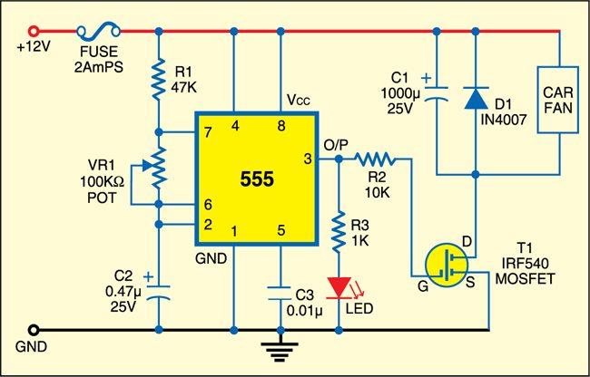
Circuit operation
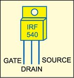
The output of the multivibrator is fed to IRF 540 MOSFET. The fan is connected to the positive terminal of the battery and drain (D) of MOSFET T1. Capacitor C1 is connected in parallel to the fan to stabilize its speed. Free-wheeling diode D1 protects the motor from back emf. A fuse is included for protection.
Potmeter VR1 is used to change the duty cycle of the multivibrator and hence the speed of the fan. If you feel that low/high level of the fan speed is not sufficient, increase/decrease the value of C2 (0.47 µF) to reduce/increase the speed of the fan.
Construction & testing
Assemble the circuit on a general-purpose PCB and enclose in a suitable cabinet. Fix the potmeter at the front side of the case, so that you can easily change the speed of the fan. Connect the battery to the fan using wires with suitable current-carrying capacities. Use red wire for positive terminal and black wire for negative terminal.
The project was first published in April 2009 and has recently been updated.

Wondered why the .47 microfarad cap
and will this work on a 30 amp car fan motor ??