 Here’s a simple clap operated electronic switch. Using this switch, you can turn on any appliance by clapping five times and turn it off by a single clap. The switch activates the appliance only if you apply the right clap code (five claps here) within the preset time (10 seconds). If you apply a wrong clap code (other than five claps) or you are unable to apply five claps within 10 seconds, the switch does not activate the appliance.

Clap Operated Electronic Switch Circuit
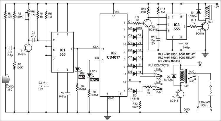
The circuit works off a 9V DC power supply. The condenser microphone converts the clap sound into an electrical signal. This electrical signal is amplified by transistor BC549 (T1). The amplified output is given to trigger pin 2 of monostable IC1, which produces a clock pulse at its output pin 3. The output of IC1 is fed to clock pin 14 of decade counter IC2.

Circuit operation
Initially, when the power is switched on, the Q0 output of IC2 is high and glowing of LED2 indicates that the switch is ready for use. All others outputs of IC2 (Q1 through Q9) are low. The Q5 output is used for activating the appliance via relay RL2.
At each clock (generated with each clap), the output of IC2 gets incremented. The Q1 output of IC2 is used to trigger the monostable (IC3). The output of IC3 is used to drive relay RL1. IC3 acts as a monostable multivibrator with a time period of approximately 10 seconds, which provides delay time to turn on an appliance even after completing the five claps before the preset time of 10 seconds. Contacts of relay RL1 separate the other output pins of IC2 (except Q5) from reset pin 15 for the preset time of 10 seconds.
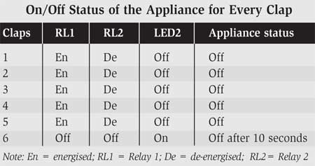
When all the five claps are applied within 10 seconds, the Q5 output of IC2 goes high and relay RL2 energises to turn on the appliance just after the de-energisation of relay RL1. The table shows the on/off condition of the appliance for every clap.
When you apply a wrong clap code, the high output of IC2 resets it via its pin 15 and the appliance doesn’t turn on.
The article was first published in May 2004 and has recently been updated.


