


 This project describes how a DC motor can be moved in forward or reverse direction using a TV or DVD remote control. The goal is to construct a simple bidirectional motor driver that uses modulated infrared (IR) 38kHz pulse train for the purpose without using any microcontroller or programming.
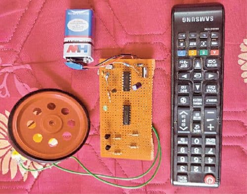
The author’s prototype is shown in Fig. 1.
Circuit and working
Circuit diagram of the project is shown in Fig. 2. It is built around IR receiver module TSOP1738 (IRRX1), decade counter 4017B (IC2), motor driver L293D (IC3), PNP transistor BC557 (T1), two BC547 NPN transistors (T2 and T3), 5V regulated power supply (IC1), and a 9V battery.

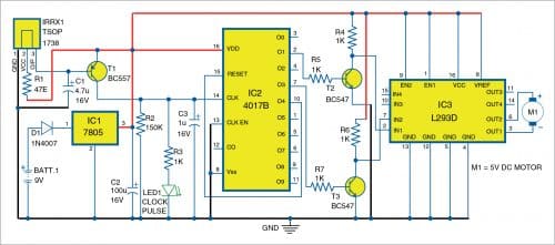
The 9V battery is connected through diode D1 to voltage regulator 7805 to generate 5V DC required for the project. Capacitor C2 (100µF, 16V) is used for ripple rejection.
Under normal conditions, output pin 3 of IR module IRRX1 is at logic high, which means transistor T1 connected to it is cut-off and so its collector terminal is at logic low. The collector of T1 drives the clock pulse of decade counter IC2.

On pointing the remote towards IR module and pressing any key, the module receives the 38kHz IR pulses from the remote control. These pulses are inverted at the collector of T1 and given to clock input pin 14 of decade counter IC2.
The arriving IR pulses increment the decade counter at the same rate (38kHz) but because of the presence of RC filter (R2=150k and C3=1µF) at clock input pin 14 of IC2, the train of pulses appears as a single pulse at the counter. Thus, on pressing each key, the counter advances by a single count only.
When the remote’s key is released, capacitor C3 discharges through resistor R2 and the clock line becomes zero. So every time the user presses and releases a key on the remote, the counter receives a single pulse at its clock input and LED1 glows to confirm that the pulse has been received.
During operation there can be five possibilities:
Case 1
When the remote’s key is pressed, the first pulse arrives and the O0 output of decade counter (IC2) goes high while pins O1 through O9 are low, which means transistors T2 and T3 are in cut-off state. The collectors of both the transistors are pulled to high state by 1-kilo-ohm resistors (R4 and R6), so both the input terminals IN1 and IN2 of motor driver L293D (IC3) become high. At this stage, the motor is in off state.
Case 2
When a key is pressed again, the second pulse arriving at CLK line increments the counter by one. That is, when the second pulse arrives, O1 output of IC2 goes high, while the remaining outputs are low. So, transistor T2 conducts and T3 is cut-off. Which means the voltage at collector of T2 goes low (IN1 of IC3) and voltage at collector of T3 becomes high (IN2 of IC3) and the inputs IN1 and IN2 of motor driver IC3 become 0 and 1, respectively. In this condition, the motor rotates in forward direction.
Case 3
When a key is pressed once again, the third pulse arriving at CLK line increments the counter by one again. So O2 output of IC2 goes high. As nothing is connected to O2 pin and output pins O1 and O3 are low, so both transistors T2 and T3 go to cut-off state.
Collector terminals of both the transistors are pulled to high state by 1-kilo-ohm resistors R4 and R6, which means input terminals IN1 and IN2 of IC3 become high. At this stage, the motor is again in off state.
Case 4
When a key is pressed once more, the fourth pulse arriving at CLK line increments the counter by one for the fourth time. Now O3 output of IC2 goes high, while the remaining outputs are low, so transistor T3 conducts. Which means the voltage at collector of T2 becomes high (IN1 of IC3) and voltage at the collector of T3 becomes low (IN2 of IC3). So, inputs IN1 and IN2 of IC3 are at 1 and 0 levels, respectively. In this condition, the motor rotates in reverse direction.
Case 5
When a key is pressed for fifth time, the fifth pulse arriving at CLK line increments the counter by one once again. Since O4 (pin 10 of IC2) is wired to Reset input pin 15 of the IC2, pressing for the fifth time brings the decade counter IC back to power-on-reset condition with O0 high.
Thus, the circuit operates as a bi-directional motor driver that is controlled with infrared remote control.
Construction and testing
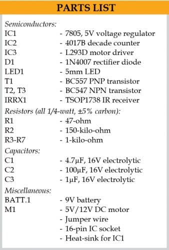
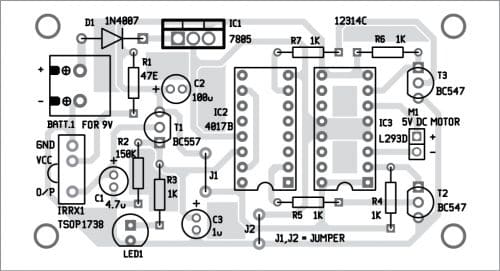
The circuit can be assembled on a Veroboard or a PCB whose layout is shown in Fig. 3. The components layout for the PCB is shown in Fig. 4.
Download PCB and Component layout PDFs: click here
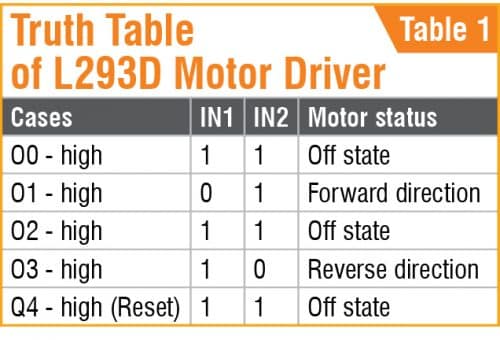
After assembling the circuit, connect 9V battery across BATT.1. Refer the Truth Table (Table 1) for operation and follow the steps described in Case 1 through Case 5 above.
Pamarthi Kanakaraja is an assistant professor (R&D cell) at K.L. University, Vaddeswaram, Guntur district, Andhra Pradesh

