


You need not be disappointed next time your digital camera shows low battery indication during a picnic trip. Just plug this digital camera adaptor into the cigarette lighter outlet of your car and connect the camera to it. The adaptor will interface the DC source and the camera battery to provide sufficient charging current to replenish the battery in one hour. The Lithium-ion or NiMH battery of the digital camera can be quickly charged with a nominal voltage of 5V and 300mA to 1A current.
Camera adaptor circuit
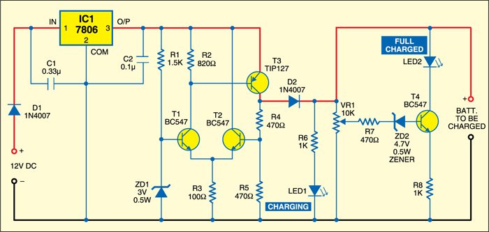
Fig. 1 shows the circuit of the digital camera adaptor. The circuit uses a differential transistor amplifier and a current amplifier to output constant voltage and the required current, respectively. NPN transistors T1 and T2 form a differential amplifier just like the inputs of an op-amp in differential amplifier configuration. The base voltage of T1 is fixed to 3 volts by Zener diode ZD1. T2 obtains the base voltage from a potential divider comprising R4 and R5 via the output rail. T1 and T2 compare the voltage at their base-emitter junctions and adjust the base current of current amplifier T3.
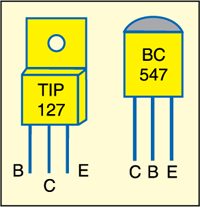
PNP transistor TIP127 (T3) is used as the current amplifier to provide sufficient current for charging. It is a medium-power Darlington transistor with a current gain of 1000. That is, if 1mA current is provided to the base of T3, its collector current will be 1A maximum. T3 works in inverter mode, so when a positive voltage is applied to the base of T1, a negative pulse will drive T3 when T1 conducts. Resistor R2 (820-ohm) provides around 1mA current to the base of T3, so it can output 1A current from its collector.

Circuit operation
Resistor R3 (100-ohm) plays an important role in the working of the differential amplifier to adjust the output voltage and current. The current passing through it is the sum of emitter currents of T1 and T2. The collector current of T2 is fixed as it is connected to 6 volts from the positive input rail.
Therefore the base current of T3 varies depending on the current flowing through resistors R2 and R3. This arrangement keeps the charging voltage and current stable, as the load resistance changes the voltage and current during charging. Any change in the output voltage is sensed by transistors T1 and T2 and the base current of T3 is adjusted accordingly.
Power supply
Power supply for the adaptor is obtained from a 12V car battery through the cigarette lighter outlet. Regulator IC 7806 (IC1) reduces the input voltage to 6 volts and restricts the output current to 1A, even if it receives a higher current. So it is safe to connect the circuit to the car battery.
Bypass capacitors C1 and C2 ensure optimal stability and transient response of IC1. Solder them close to the leads of IC1. Maximum steady current available from IC 7806 depends on the input voltage, heat-sinking and lead length. Since IC1 receives high current at its input, adequate heat-sinking of the IC is a must to dissipate heat. Maximum power dissipation of the IC is 0.5 watt.
LED1 and LED2 are used to indicate charging and full-charge conditions. When the digital camera is connected to the adaptor, LED1 lights up indicating ‘charging,’ while LED2 remains off. Zener diode ZD2 (4.7V) acts as a diode switch to drive transistor T4 into conduction only when the terminal voltage of the battery increases above 5.3 volts (Zener voltage 4.7V+0.6V). Adjust potmeter VR1 such that T4 conducts and LED2 light up only if the battery under charging holds more than 5.3 volts. Diodes D1 and D2 act as polarity protectors.
Construction & testing
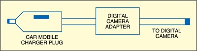
Assemble the circuit on a general-purpose PCB and enclose in a suitable cabinet. Use a car mobile charger plug to provide power to the circuit from a cigarette lighter outlet. The plug has nothing inside, except a fuse. Connect the input wires to the plug with correct polarity. Use a suitable pin to take the output to the digital camera.
If the cigarette lighter outlet is not available, power can be tapped directly from the car battery. Current drain from the adapter depends on the status of the battery. During charging, it ranges from 300 mA to 1A.
The project was first published in July 2009 and has recently been updated.
