


We build the Arduino based Multi-house Water Pump Control System. Here we are going to explain step-by-step, how you can make your own Water Pump Controller.
But before that, we need to understand why we made this, and where you can use this project.
Basically, in a row of rented houses that share a common pump motor for their water supply, issues arise when it comes to splitting the electricity bill. The shared motor often runs on a common main supply, and it is challenging to divide the electricity charges properly among tenants due to variations in water consumption.

The water pump control circuit presented here offers a solution by allowing the common pump motor to run on the supply specific to each house whenever a tenant switches on the motor for their water needs.
To achieve this, each house is equipped with individual distribution discharge lines with manual valves that connect to their overhead water tanks. Before starting the pump to fill their overhead tank, a tenant must ensure that their respective discharge valve is open while the others’ valves are closed.
POC Video Tutorial In English:
| Bill of Materials | ||
| Components | Description | Quantity |
| Arduino nano board | MCU | 1 |
| IC-7812 (IC6) | 12V voltage regulator | 1 |
| ULN2003 (IC5) | Relay driver | 1 |
| PC817 (IC1-IC4) | Optocoupler | 4 |
| FZ5.1A (D1-D4) | Zener diode | 4 |
| 1N4007 (D5, D6-D16) | Diode | 16 |
| LED (LED1-LED4 | 5 mm LED | 4 |
| Resistor (R5-R8) | 10K, 1/4W | 4 |
| Resistor (R1-R4) | 15K, 2 W | 4 |
| Capacitor (C1-C4) | 100uF, 25V electrolytic | 4 |
| Capacitor (C5, C6) | 0.01uF, ceramic disc | 2 |
| Relays (RL1-RL4) | 12V DC, 6A, 2 C/O | 4 |
| Glass-fuses (F1-F4) | 250V/500V, 16A | 4 |
| AC to DC power adapter | 15V, 1A Output | 1 |
| Power terminal block strip | (12 Ways) | 1 |
This innovative circuit enables the pump to run on power from different main supplies, even accommodating different phases in a three-phase system. The setup enables more accurate billing of electricity consumption based on individual usage.
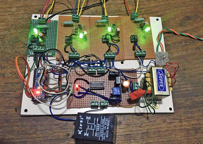
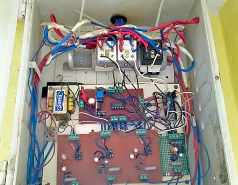
Fig. 1 showcases the prototype and the Bill of Materials table lists the components required to build this Water Pump Control project.
Also Check: Interesting Arduino Projects
Water Pump Controller Circuit
The circuit diagram of the multi-house water pump control system, shown in Fig. 2, is based on an Arduino Nano board (MOD1), four PC817 optocouplers (IC1 through IC4), relay driver IC ULN2003 (IC5), a 12V voltage regulator (IC6), and various other components.
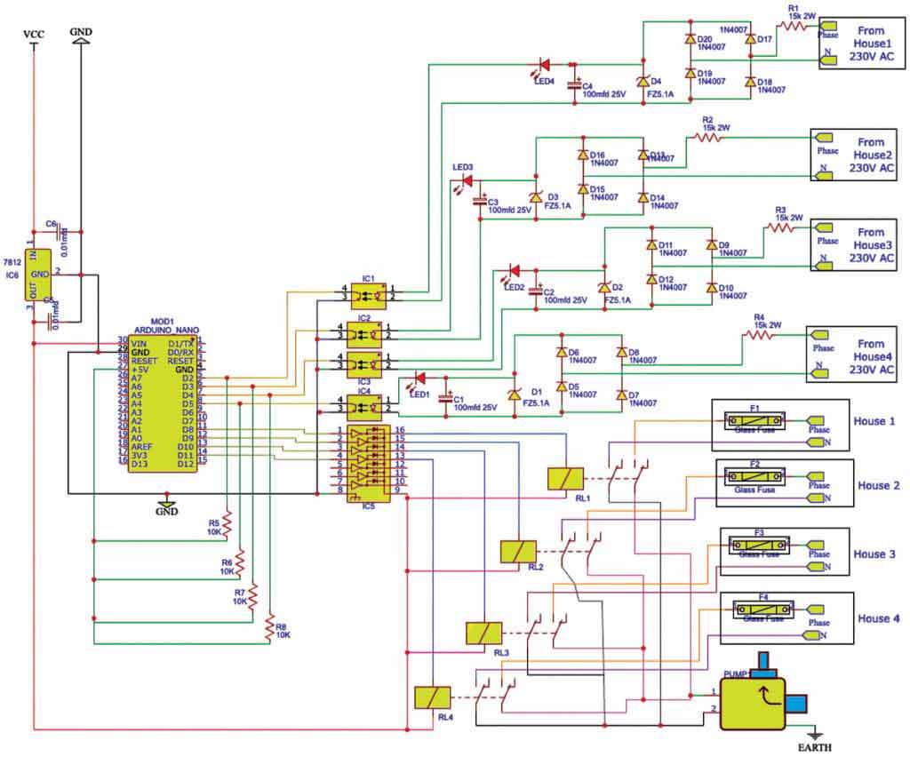
The circuit can be divided into two sections:
- Power Circuit
- Control Circuit
The Power Circuit includes the pump, fuses, zener diodes, diodes, and more. It consists of the pump (motor) power supply receiving terminal blocks from each house, motor on/off power switches, power fuses (F1 through F4) for short-circuit protection (miniature circuit breakers MCB of equal ratings can be used), motor switching relays (RL1 through RL4), and an output terminal block for motor cable connections.
The Control Circuit is built around the Arduino Nano (Board1) and IC1 through IC6. It uses a 12V, 1A voltage regulator to provide 12V DC regulated power supply to the Arduino Nano board, relays (RL1-RL4), and optocouplers (IC1-IC4).
Multi-house Water Pump Control System -Working
The optocouplers sense power supply availability and motor switch status in all the houses, interfacing with the Arduino Nano board and relay driver IC ULN2003. The Arduino Nano board provides 5V power supply, which is available at its 5V terminal for the control circuit’s inputs and outputs.
The Arduino Nano board receives input from a house’s motor on/off switch through optocouplers (230V AC to 5V). The optocoupler IC PC817 provides electrical isolation, ensuring safe operation. When an optocoupler receives 230V AC supply, it switches the voltage from 5V to zero at the connected Arduino Nano pins (D2 through D5).
This means that a logic high at an Arduino input is interpreted as the motor switch being off, and a logic low as the motor switch being on.
The Arduino Nano board operates according to the embedded program. This program is designed to handle the demands of up to four houses sharing a single motor.
However, it can be adjusted for just two or three houses as well. For more than four houses, both the program and hardware require modification.
The houses are prioritized based on their door numbers, ascending in order. For example, if there are four houses with door numbers 10, 11, 12, and 13, house number 10 receives the highest priority and starts the motor after a 60-second delay. Subsequently, all other houses are prevented from using the motor.
After house number 10 has completed its cycle, the motor can be activated again after a 61-second delay if house number 11 requires it. This pattern continues for the other two houses with decreasing priority, with delays of 62 and 63 seconds, respectively.
Whenever a house turns on the motor switch, its Arduino input pin (D2 through D5) goes low, and the corresponding output pin (D8 through D11) becomes high after the preset delay. This delay is based on the ascending order of input numbers, and the relay is energized through the ULN2003 driver.
As a result, the motor runs on power from the respective house, and the program prevents other house relays from activating.
Even if other houses turn on their motor switches, the motor won’t change its supply source, until the current user house turns off their motor switch.
If two or more houses turn on their switches simultaneously, the motor starts in priority order, as explained earlier.
The built-in LED of the Nano is programmed to flash (0.5 seconds on, 0.5 seconds off) continuously to indicate that the program loop is active.
If the flashing stops, it indicates a hung state of the Arduino Nano, which can be resolved by resetting the Nano by pressing the reset button or by power-cycling the control supply.
Arduino Code
The software is written in the Arduino programming language using Arduino IDE version 1.8.7.
Before uploading the ‘rentedhouses4.ino’ sketch/program to the Arduino Nano, ensure that the ‘elapsedMillis’ library function is available in the Arduino IDE.
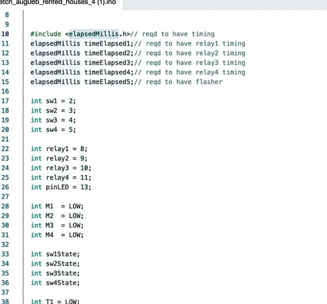
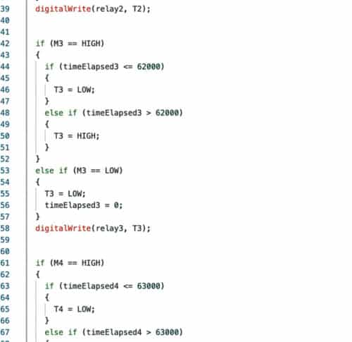
Upload the sketch to the board after selecting the appropriate board and port name. Fig. 3 shows a code snippet with pin definitions for inputs and outputs, while Fig. 4 displays a code snippet with time lapse logic for each house.
Construction and Testing
Begin by uploading the source code ‘rentedhouses4.ino’ to the Arduino Nano using a laptop or desktop computer. Assemble the circuit on a breadboard or a general-purpose PCB, and connect the Arduino Nano board with the uploaded source code to it.
Provide an unregulated supply of 15V to 18V DC across the Vcc and GND. Double-check your circuit connections to match the schematic diagram shown in Fig. 2.
For the control circuit’s 230V AC power supply, use a common source, preferably the house owner’s supply (if different from the four rented houses). This allows the owner to control the motor’s operation.
Ensure that only one relay operates at any given time, with a delay of 60, 61, 62, or 63 seconds based on house priority. After confirming this, proceed with the power circuit wiring as per the schematic diagram in Fig. 2.
Both power and control circuits should be assembled and wired within a metal enclosure, placed conveniently close to the motor or the houses (consider cable lengths), and connect the input and output motor power cables.
Testing the project is simple and straightforward.
After connecting, energize only the control circuit’s 230V AC supply and test the operation of output relays by providing 230V AC supply to opto inputs one by one initially and then simultaneously to all opto inputs afterward.
At any moment, only one relay should operate, with a delay of 60, 61, 62, and 63 seconds, based on house priority.
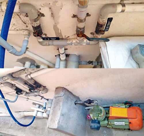
Fig. 5 shows the water valve and water motor setup for the houses, while Fig. 6 shows the complete device setup in the building for different houses.
Precautions
1. Do not forget to connect a safety earth cable for the metal enclosure (use two separate earth wires if a 3-phase supply system is involved).
2. Power fuses for short-circuit protection (glass/ceramic) should be rated for 500V AC if the supplies are from different single phases (R, Y, B) of a 3-phase system; otherwise, 250V AC is sufficient.
3. 12V DC relay contacts are rated for 6A AC, so ensure the motor’s current rating does not exceed 6A.
4. Additional features, such as motor ON indication near each house’s motor switch and automatic operation of pump motor discharge valves with solenoid valves, can be added, but this would involve additional cost and wiring, which is not included in this design.
P. Balasubramanian is a retired scientific officer from Nuclear Power Corporation of India Ltd (NPCIL). His areas of interest include microcontrollers and power electronics