


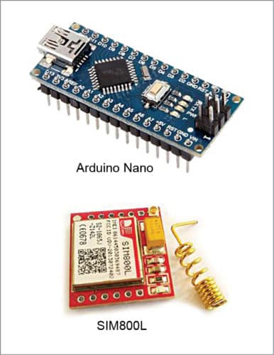
 This simple GSM security switch project is based on Arduino Nano microcontroller (MCU) and SIM800L GSM modem (Fig. 1).
The cellular-based alert system is configured to send an SMS in response to a security switch action. When the security sensor switch input recognises an event, the system sends a customised alert message to a predefined cellphone number.
Circuit and working
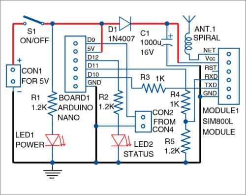
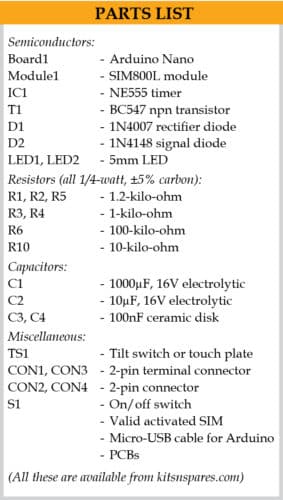
The circuit diagram of the GSM security switch is shown in Fig. 2. It is built around Arduino Nano board (Board1), SIM800L GSM modem (Board2), 5V, 2A power supply and a few other components.
Arduino Nano runs on 5V DC supply, and the modem gets around 4.3V DC. When hardware setup is ready, upload the sketch to Arduino Nano board. Power up Arduino Nano and GSM, and take a trial run. Do not forget to insert a valid micro-SIM card in the slot provided in GSM modem before powering up the system. Normally, the SIM card registers automatically to the home network within a couple of seconds. Onboard LED indicator of SIM800L modem will blink once every two to three seconds (not continuously) when it successfully registers to the home network.
A micro-USB cable is used to connect Arduino Nano with the PC or laptop for uploading the source code.
After uploading GSMsecurity.ino to Arduino, remove the micro-USB cable and connect 5V, 2A power supply to the circuit. LED1 is the power-on indicator and LED2 is the system status indicator.
Resistors R1 and R2 are current limiters, while the rest (R3 through R5) form a tricky logic-level translator setup. Add diode D1 and buffer capacitor C1 to Vcc line of SIM800L module.
Connecting pin D9 of Arduino to ground will trigger an alert in the cellphone. That is, if a low signal is received through a sensor connected across connector CON2, it will trigger the alert generator instantly. You can use this circuit as a security alert system, such as for vehicle anti-theft alert system, burglar alarm and so on.
Software
The software is written in Arduino programming language. GSMsecurity.ino sketch is compiled and uploaded to Arduino Nano board using Arduino IDE.
There are many featured Arduino libraries that you can try (the one from Cristian Steib is [email protected]), but the sketch included here will work well for this application without such libraries.
Here, communication between Arduino Nano and SIM800L goes over SoftwareSerial library and uses standard AT commands. So, simply use this sketch after changing the recipient’s phone number (phone number for receiving the alert message).
Interfacing with the sensor
You can connect sensor input at CON2 with such sensors as reed switches, photo-resistors/diodes and thermostats, allowing for considerable customisation of the security system. This also adds a number of capabilities including recognition and response to momentary inputs from a laser trip wire, impact sensor, door/gate sensor, etc.
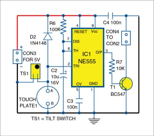
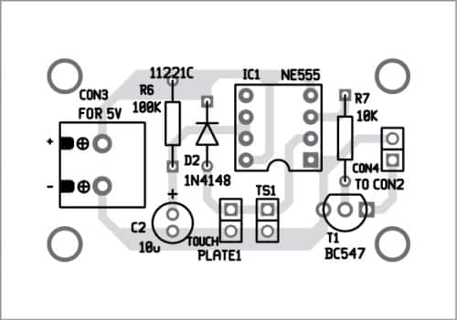
An optional sensor front-end model for the security system using an inexpensive touch/tilt sensor circuit is described here, as shown in Fig. 3. It is built around a touch plate, tilt switch (TS1), NE555 timer (IC1), BC547 npn transistor (T1), 5V power supply and a few other components.
Construction and testing
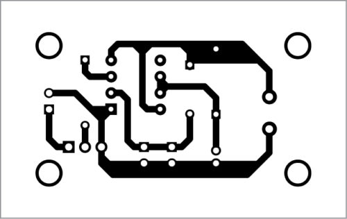
A PCB layout of the GSM security switch is shown in Fig. 4 and its components layout in Fig. 5. Upload the source code to Arduino Nano and then insert it into the PCB. Solder the spiral antenna on SIM800L module.
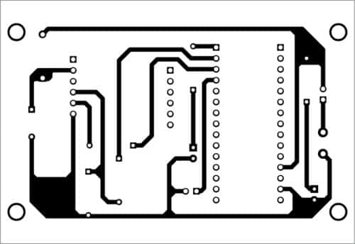
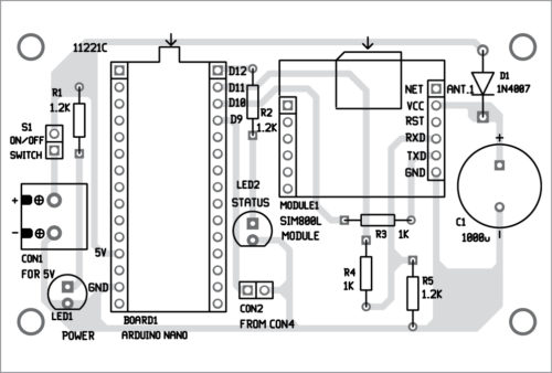
Mount Arduino Nano and SIM800L on the PCB. Connect 5V, 2A regulated power supply across CON1. When security switch connected to pin D9 of Arduino Uno goes low momentarily, an alert SMS carrying ‘Warning, Intrusion’ message will be received on the cellphone.
A PCB layout of the tilt/touch sensor circuit is shown in Fig. 6 and its components layout in Fig. 7. Assemble the circuit on the PCB and fix either the touch plate or tilt sensor or both, as shown in the circuit diagram of Fig. 3. Connect 5V DC regulated power supply across CON3. Then, connect CON2 to sensor circuit CON4 using a two-wire cable.
Download PCB and Component Layout PDFs: click here
Download Source Code: click here
On touching sensor plate1 or tilting sensor TS1, output of IC1 goes high and transistor T1 conducts. This, in turn, pulls pin D9 of Arduino to ground through T1. This action triggers GSM switch and generates an SMS alert message, which is received on the cellphone.
The project is now ready to use. Place the circuit at a suitable location to protect the asset (like electronic safe, vehicle, etc) or property.
T.K. Hareendran is founder and promoter of TechNode Protolabz

Plzzz give me this project Arduino program
The source code is present in the article itself.