


Android smartphones are undoubtedly the most popular gadgets these days. You will find various apps on the Internet that exploit inbuilt hardware in these mobile phones, such as Bluetooth and Wi-Fi, to control other devices. Presented here is a phone controlled robot that can be controlled via an app on your mobile. The control commands are sent via Bluetooth and the robot has such features as:
1. It can be controlled from Android smartphones by touch or voice commands
2. The speed of the robot can also be controlled
3. The robot will sense and inform to the phone its distance from the nearest obstacle
4. It will also send information about the direction in which it is moving
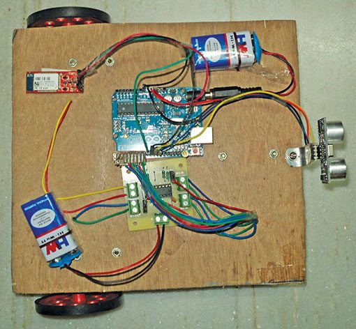
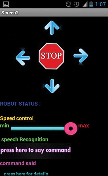
Fig. 1 shows the author’s prototype of the robot and Fig. 2 shows the app running on an Android phone to control the robot.

Circuit and working
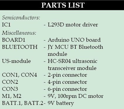
Fig. 3 shows circuit diagram of the Android phone-controlled robot. The circuit is built around an Arduino UNO board (BOARD1), ultrasonic transceiver module HC-SR04, Bluetooth module JY MCU BT, motor driver L293D (IC1), DC motors M1 and M2, and a few common components.
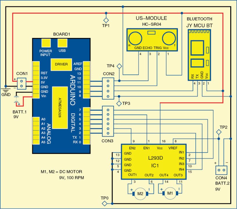
The circuit uses two 9V batteries—one to power the Arduino board and the other to power the motors, as shown in Fig. 3. Regulated 5V supply for rest of the circuit is provided by the Arduino board itself. LED on the board indicates presence of power supply.
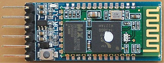
Bluetooth module. Bluetooth module JY MCU BT used in the project can be connected to any device, via built-in UART interface, to communicate with other Bluetooth-enabled devices such as mobile phones, handheld computers and laptops. The module runs on a 3.6V to 6V supply. Fig. 4 shows a picture of the Bluetooth module.
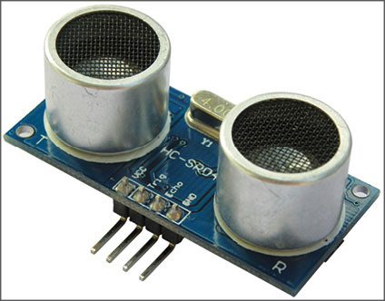
Ultrasonic transceiver module. Ultrasonic transceiver module HC-SR04 uses sonar, like bats and dolphins, to determine distance to an object. It offers excellent non-contact range-detection of 2cm to 400cm with high accuracy and stable readings in an easy-to-use package. It comes complete with an ultrasonic transmitter and a receiver module. Fig. 5 shows the ultrasonic transceiver module.
To start the measurement of distance, pin 2 (TRIG) of the module should receive a high pulse for at least ten microseconds. The pulse will initiate the module to transmit eight cycles of ultrasonic burst at 40 kHz and wait for the reflected ultrasonic burst. When the sensor detects the reflected ultrasonic burst, it sets pin 3 (ECHO) to ‘high’state. Duration of the reflected pulse depends on the distance from the obstacle, which can be easily calculated as:
Distance (in centimetres) = T/58
where, T = Width of pulse at ECHO pin in microseconds
Arduino Uno board. Arduino is an open source electronics prototyping platform based on flexible, easy-to-use hardware and software. It is intended for artists, designers, hobbyists and anyone interested in creating interactive objects or environments.
Arduino Uno is a board based on ATmega328 microcontroller. It has 14 digital input/output pins, six analogue inputs, a USB connection for programming the on-board microcontroller, power jack, an ICSP header and a reset button. It is operated with a 16MHz crystal oscillator and contains everything needed to support the microcontroller.
The board is very easy to use as the user simply needs to connect it to a computer with a USB cable, or power it with an AC-to-DC adaptor or battery to get started. The microcontroller on the board is programmed using Arduino programming language using Arduino development environment.
Pins 8 and 9 of BOARD1 are connected to pins Tx and Rx of the Bluetooth module, respectively. Pins 10 and 11 are connected to trigger (TRIG) and echo (ECHO) pins of HC-SR04, respectively. Pins 2 through 7 of BOARD1 are the output pins, which are connected to IC1 for controlling the motors. Pins 2, 3 and 4 of BOARD1 are connected to IN3, EN2 and IN4 of IC1 to control motor M1, and pins 5, 6 and 7 are connected to IN1, EN1 and IN2 of IC1 to control motor M2. EN1 and EN2 are used to control the speeds of the motors.
The control commands for the robot are sent from the phone using the app shown in Fig. 2. You can send the commands either by touching on various options on the phone’s screen or through speech commands. Corresponding to control commands you select on the app, the related data is sent through Bluetooth of the phone. Data transmitted by the phone is received by Bluetooth module at the robot end. The received data is fed to pin 8 of BOARD1. The microcontroller on BOARD1 processes the received data and drives motors accordingly.
The robot also sends back the status. In the app you can see label ‘Robot Status,’ below which you can see the direction in which robot is moving. The robot continuously sends back information about the distance from the closest obstacle to the phone, and if it reaches too close to an obstacle the robot stops automatically.
Software
The software for the robot is written in Arduino programming language. The Arduino UNO is programmed using Arduino IDE software. Atmega328 on Arduino UNO comes with a boot loader that allows you to upload new code to it without using an external hardware programmer. It uses STK500 protocol to communicate. You can bypass the boot loader and program the microcontroller through ICSP (in-circuit serial programming) header, but using boot loader programming is quick and easy. Select the correct board from ‘Tools→Board’ menu in Arduino IDE and burn the program (sketch) through standard USB port in the computer.
Download PCB and Component Layout PDFs: click here
Download Source Code: click here
The procedure for installing Android app on the phone is as follows:
1. Download the app (Android_BOT.apk) from the link and copy it to your Android smartphone (or tablet).
2. Run the file, and when it asks you ‘Complete action using,’ click on ‘Package installer’ and then click ‘Install.’
3. You also have to install voice-search and a text-to-speech app from play store if you want to control the robot through speech.
Please note, you have to change the baud rate of the Bluetooth module on the robot to 57600 using AT command.
Construction and testing
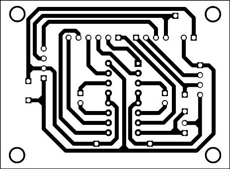
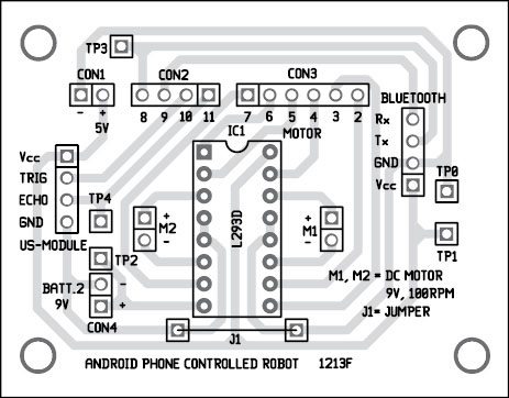
An actual-size, single-side PCB layout for the phone-controlled robot is shown in Fig. 6 and its component layout in Fig. 7. Assemble the circuit on the recommended PCB to minimise assembly errors. Use IC base for motor driver IC1.
Follow the steps below to get the robot running the first time:
1. Provide power supply to the robot by connecting the batteries.
2. Pair the Bluetooth module with Android phone. While pairing it will ask you the password. Type 1234, which is the default password of Bluetooth module.
3. Run the already installed app in the phone. Press on the welcome screen to get the main interface.
4. Select ‘Select Device’ (make sure the Bluetooth is on), then select Bluetooth module from the list of Bluetooth devices scanned and select ‘Connect.’ It will take five to ten seconds to connect. After connection, it will notify you that Bluetooth is connected. Now it is time to start playing with the robot.
5. Slide the slider to the right (or left) to set the speed, and select the arrows to move the robot in corresponding directions.
6. To control the robot with speech commands (forward, backward, left, right and stop) select ‘Say Command’on the app screen. You can also see the commands that are spoken by you. We need to pronounce the commands clearly.
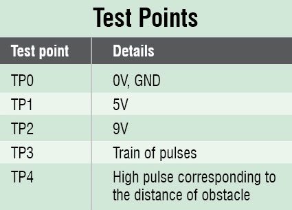
To test the circuit for proper functioning, verify there is correct 5V supply for the circuit at TP1 with respect to TP0. Also verify the 9V supply for the motors at TP2. Transmitted data by the Bluetooth can be observed at TP3. Echo from the ultrasonic module can be checked at TP4 using an oscilloscope.
The author is a third-year B.Tech student of electronics and communication engineering in RVR&JC College of Engineering, Guntur
i m not getting the app which u specified can u plz send me the app for my emal id [email protected]
Can I use HC-05 Bluetooth module instead of the JY MCU Bluetooth module?
My blue tooth module is getting paired but the robot is not moving, what might be the error? Sir please reply
yes, u can use HC-05 bluetooth module
No. If you use HC-05 module, you have to use 5V to 3.3V level converter or some other arrangement. HC-05 bluetooth module should not be directly interfaced to 5V TTL level on Arduino board.
you connect to the 3.3v in arduino board
I can’t find the code of android. Can you give me, my email: [email protected]
The source code is present within the article itself.
Instead of JY MCU BT bluetooth module can i use HC-06 module?
Same query was asked by one of the memebers before. The answer is no. If you use HC-05 module, you have to use 5V to 3.3V level converter or some other arrangement. HC-05 bluetooth module should not be directly interfaced to 5V TTL level on Arduino board.
Is it necessary to change baud rate of the bluetooth module. If I do not change the baud rate and let it be default what will happen? if I arrange separate 3.3v supply for bluetooth module, then can I use ‘HC-05’ module?
i m not getting the app which u specified can u plz send me the app for my emal id
[email protected]
can we use any app to control the robot?
You need to download the app from: http://www.efymag.com/admin/issuepdf/Android_phone.rar
Sir,
Will you please tell me that how much cost it would take to make?
And from where I can buy it?
I live in Kanpur.
Can I get your contact no.
The approx. cost of the project with simple chassis will be below Rs 3000. We do not have the complete kit of this project right now and also we have no idea where you can buy this project, sorry.
I have found the apk file for the android app but i need the android app code that is written in java. Would you be kind enough to send it to me via email
at [email protected]
Hii Sir, pls tell me Which software and language easy to develope android application for this topic.
What is the transmission range??
Sir please send the Arduino code to my mail
[email protected]
The source code given above is of invalid format and cant be opened .Plz help me regarding this so as to get the project completed.
in the app i want to change the name from in front page what can i do ?
could you please send me the Android app project at [email protected] it will be a great help
thanks from Nepal
send me the app link to [email protected]
i can’t get the code
please mail: [email protected]
The source code is present at the end of the article.
Plzz send news related this articale in my email…
Sir plz sent the app name to my mail id
[email protected]
Pls send me the app link to [email protected]
Can u plz send me codes
Hi Vatsalya, the source code is present at the end of the article.
Coding of audirno?
What is the app used in this project and send the coding to my mail [email protected]
i m not getting the app which u specified can u plz send me the app for my emal id
There is problem in application. Pls improve it sir..it ia not working
Kindly elaborate your query.
Hello,
I tried the whole setup given by this article, it worked at the first time (with HC-05) ! but after replacing the 9V motor and battery with 6V gear motor and battery it behave weird! I took the 9V supply to arduino same, just change the motor n battery. Motor driver indicator continuously blinking but motor doesn’t move. After that android apps connect with BT Module and while i press any key the BT automatically disconnect! And showing this message: Error 516:Unable to write:Broken pipe.
Help please ASAP. Thanks
Can you send me the .aia file, please!
Attach a link to this website or send me [email protected]
tnx very much
You are most welcome.
Sir,
Will you please tell me that how much cost it would take to make
Sir please send the Arduino code to my mail
The source code is present in the article itself.
Sir please send the Arduino code to my mail
[email protected]
Hi can you please send me the making video and code of this project if you have
Please send such request to [email protected]
I want to develop my android application that will help to drive a car, how can I do?